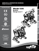
3.06 78 9.19 Original Instructions 233 7.19 Certified 183 Quality 3/8" NPT AIR EXHAUST SUCTION PORT(OPTIONAL) 1/2" NPT 79.12 1.76 44.61 3.78 DISCHARGE PORT 96 1/2" NPT 6.12 155 Model S05 4X .38 MTG. HOLE 10 Metallic Design Level 1 AIR INLET 1/4 NPT 10.48 266.17 7.75 197 5.60 142.32 SUCTIO 1/2" RF 4X ON A 1: PUMP SPECS SERVICE & OPERATING MANUAL 3.12 2: INSTAL & OP 6.90 175.13 3: EXP VIEW 1.25 32 2.00 51 Quality 1.42System 36.12Certified ISO 9001 7.
Safety Information IMPORTANT WARNING When used for toxic or aggressive fluids, the pump should always be flushed clean prior to disassembly. Read the safety warnings and instructions in this manual before pump installation and start-up. Failure to comply with the recommendations stated in this manual could damage the pump and void factory warranty. Before maintenance or repair, shut off the compressed air line, bleed the pressure, and disconnect the air line from the pump.
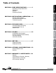
SECTION 5: WET END......................................17 • Diaphragm Drawings • Diaphragm Servicing SECTION 6: OPTIONAL CONFIGURATIONS.....19 • Solenoid Shifted Air Valve • Dual Port SECTION 7: WARRANTY & CERTIFICATES.....21 • Warranty • CE Declaration of Conformity - Machinery • ATEX Declaration of Conformity • ATEX Summary of Markings sandpiperpump . com s05mdl1sm-rev0814 2: INSTAL & OP 3: EXP VIEW 4: AIR END SECTION 4: AIR END........................................
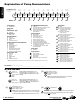
1: PUMP SPECS Explanation of Pump Nomenclature Your Model #: (fill in from pump nameplate) S __ ____ __ __ Pump Brand Pump Size Check Valve Design Level S XX X X Model #: Pump Brand S __ __ Wetted Diaphragm/ Check Valve Non-Wetted Material Check Valve Seat Material X A Y C 05 1/2" †P Check Valve Type Solid Ball X X X __ __ __ ____ Porting Options Pump Style Pump Options Kit Options X X X XX Kit Options 00. None P0. 10.30VDC Pulse Output Kit P1. Intrinsically-Safe 5.
Performance S05 METALLIC 100 2 (3.5) 4 (7) 6 (10) 8 (13.5) 100 P SI (6.8 Bar) SCFM (M /hr) 10 (17) 12 (20) 6 HEAD SOLIDS-HANDLING • Up to .125 in. (3mm) HEADS UP TO • 125 psi or 289 ft. of water (8.6 bar or 86 meters) 4 3 60 PSI 40 40 PS 20 DISPLACEMENT/STROKE • .026 Gallon / .098 liter 0 (4.08 B ar) I (2.72 20 PSI 1 0 16 (27) ar) 18 (30) 60 2 MAX OPERATING PRESSURE • 125 psi (8.6 bar) metallic center • 100 psi (7 bar) non-metallic center (5.44 B 0 20 (33.75) Bar) (1.
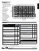
1: PUMP SPECS S05 Metallic (Aluminum Model) Dimensions in Inches. Dimensional tolerance: ±1/8" DISCHARGE PORT 1/2” NPT (INTERNAL) 1” NPT (EXTERNAL) ENCAPSULATED MUFFLER: 3/8” NPT EXHAUST PORT FOR OPTIONAL PIPING MUFFLER STYLES OR PIPING EXHAUST AIR IN SUBMERGED APPLICATIONS.
1: PUMP SPECS S05 Metallic - Stainless Steel NPT Dimensions in inches (mm dimensions in brackets). Dimensional Tolerance:±1/8" (± 3mm) The dimensions on this drawing are for reference only. A certified drawing can be requested if physical dimensions are needed. DISCHARGE PORT(OPTIONAL) 1/2" NPT DISCHARGE PORT(OPTIONAL) 1/2" NPT 6.90 175.13 6.90 175.13 10.87 275.99 10.87 10.24 275.99 260.14 10.24 260.14 3.12 79.12 3.12 79.12 1.76 44.61 1.76 44.61 3/8" NPT AIR EXHAUST 3/8" NPT AIR EXHAUST 10.54 267.
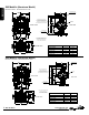
1: PUMP SPECS Dimensional Drawings S05 Metallic - Stainless Steel ANSI Flange Dimensions in inches (mm dimensions in brackets). Dimensional Tolerance:±1/8" (± 3mm) The dimensions on this drawing are for reference only. A certified drawing can be requested if physical dimensions are needed. 10.26 261 10.26 261 3.08 78 3.08 78 3.78 96 3.78 .38 10 .38 DISCHARGE PORT 1/2" RF ANSI (#150) FLANGE DISCHARGE 4X .62 [16]PORT HOLES EQ. SPACED 1/2"ARF ANSI FLANGE ON 2.38(#150) [60] BOLT CIRCLE 4X .
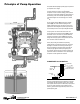
Principle of Pump Operation Air-Operated Double Diaphragm (AODD) pumps are powered by compressed air or nitrogen. As inner chamber pressure (P1) exceeds liquid chamber pressure (P2), the rod ⑤ connected diaphragms shift together creating discharge on one side and suction on the opposite side. The discharged and primed liquid’s directions are controlled by the check valves (ball or flap)⑥ orientation.
Recommended Installation Guide Available Accessories: 1. Surge Suppressor 2. Filter/Regulator 3.
Troubleshooting Guide Pump Cycles Once Pump Will Not Operate / Cycle Pump Cycles and Will Not Prime or No Flow Pump Cycles Running Sluggish / Stalling, Flow Unsatisfactory Product Leaking Through Exhaust Premature Diaphragm Failure Unbalanced Cycling Potential Cause(s): Deadhead (system pressure meets or exceeds air supply pressure). Air valve or intermediate gaskets installed incorrectly. Bent or missing actuator plunger. Pump is over lubricated. Lack of air (line size, PSI, CFM).
Composite Repair Parts Drawing 10 ILLUSTRATION SHOWS DIRECTION OF DIAPHRAGMS 13 DIAPHRAGM CONFIGURATION DETAIL NOTE TO ASSEMBLY The diaphragms for both configurations shown above are to be installed with convolutions facing towards center of pump 10 8 9 25 37 20 9 Alum Center 9a Poly Center Torque: 50 in/lbs Aluminum ONLY 23 3 29 22 18 9 10 10 37 32 28 37 33 35 21 12 10 4 1 2 29 10 Alum Center 10a Poly Center 6 31 15 37 37 38 29 29 36 17 29 27 37 29 37 9 30 16 5 24 11
Item 1 Part Number 031.191.000 031.166.000 031.168.000 031.168.002 031.167.000 031.186.000 031.169.000 031.186.003 031.186.002 031.191.002 031.191.003 2 050.022.600 050.027.354 050.027.356 050.027.357 050.027.360 050.027.364 050.027.365 3 095.091.000 095.091.001 095.116.000 4 114.023.157 114.023.551 114.023.559 5 115.152.151 6 132.034.360 7 135.036.506 8 165.110.157 165.110.551 165.110.559 9 170.044.115 170.044.115 170.044.330 9A 171.062.115 10 170.045.115 170.045.330 170.
3: EXP VIEW Material Codes 000 ����Assembly, sub-assembly; and some purchased items 010 ����Cast Iron 015 ����Ductile Iron 020 ����Ferritic Malleable Iron 080 ����Carbon Steel, AISI B-1112 110 �����Alloy Type 316 Stainless Steel 111 �����Alloy Type 316 Stainless Steel (Electro Polished) 112 �����Alloy C 113 �����Alloy Type 316 Stainless Steel (Hand Polished) 114 �����303 Stainless Steel 115 �����302/304 Stainless Steel 117 �����440-C Stainless Steel (Martensitic) 120 ����416 Stainless Steel (Wrought Marten
Air Distribution Valve Assembly 1-I 1-H 1-F 1-F 1-G 1-E 1-C 1-D 1-A 1-C 1-D 1-E 1-B 1-F Main Air Valve Assembly Parts List Item 1 1-A 1-B 1-C 1-D 1-E 1-F 1-G 1-H 1-I Part Number 031.191.000 031.132.000 095.106.157 132.038.357 165.128.157 171.076.330 560.101.360 530.031.550 165.109.551 706.027.330 Description Valve Assembly Sleeve and Spool Set Valve Body Bumper End Cap Hex Flange Capscrew 1/4-20 x .75 O.
4: AIR END Air Distribution Valve Assembly for Polypropylene Center Sections Main Air Valve Assembly Parts List Air Distribution Valve Servicing See repair parts drawing, remove screws. Step 1: Remove end cap retainer (1-G). Step 2: Remove end cap (1-E). Step 3: Remove spool part of (1-B) (caution: do not scratch). Step 4: Press sleeve (1-B) from body (1-A). Step 5: Inspect O-Rings (1-C) and replace if necessary. Step 6: Lightly lubricate O-Rings (1-C) on sleeve (1-B).
Air Valve with Stroke Indicator Assembly 1-K 1-H 1-J 1-B 1-F 1-B 1-D 1-E 1-C 1-l 1-I 1-D 1-C 4: AIR END 1-F 1-A 1-E 1-G Air Distribution Valve Servicing See repair parts drawing, remove screws. Step 1: Remove end cap retainer (1-G). Step 2: Remove end cap (1-E), bumper (1-D). Step 3: Remove spool part of (1-B) (caution, do not scratch). Step 4: Press sleeve (1-B) from body (1-A). Step 5: Inspect O-Rings (1-C) and replace if necessary. Step 6: Lightly lubricate O-Rings (1-C) on sleeve (1-B).
4: AIR END Pilot Valve Assembly Pilot Valve Servicing With Pilot Valve removed from pump. Step 1: Remove snap ring (3-F). Step 2: Remove sleeve (3-B), inspect O-Rings (3-C), replace if required. Step 3: Remove spool (3-D) from sleeve (3-B), inspect O-Rings (3E), replace if required. Step 4: Lightly lubricate O-Rings (3-C) and (3-E). Reassemble in reverse order. Pilot Valve Assembly Parts List For Models Equipped with Aluminum Midsections Item Part Number Description 3 095.116.
Intermediate Assembly 26 21 7 25 4 21 7 25 Intermediate Assembly Drawing Step 1: Remove plunger, actuator (25) from center of intermediate pilot valve cavity. Step 2: Remove Ring, Retaining (26), discard. Step 3: Remove bushing, plunger (7), inspect for wear and replace if necessary with genuine parts. Step 4: Remove O-Ring (21), inspect for wear and replace if necessary with genuine parts. Step 5: Lightly lubricate O-Ring (21) and insert into intermediate.
Diaphragm Service Drawing 37 11 20 30 34 6 11 31 14 11 27 20 30 15 Use With TPE Diaphragms Only 37 37 14 Torque: 120 in/lbs Diaphragm Orientation Install diaphragm and spacer as shown above. 11 Diaphragm Service Drawing - with Overlay 37 11 16 15 34 30 6 31 11 5: WET END 16 27 17 14 11 37 30 37 Torque: 120 in/lbs 14 Diaphragm Orientation Install diaphragm and spacer as shown above.
Diaphragm Servicing Step 1: With manifolds and outer chambers removed, remove diaphragm assemblies from diaphragm rod. DO NOT use a pipe wrench or similar tool to remove assembly from rod. Flaws in the rod surface may damage bearings and seal. Soft jaws in a vise are recommended to prevent diaphragm rod damage. Step 1.A: NOTE: Not all inner diaphragm plates are threaded. Some models utilize a through hole in the inner diaphragm plate.
Solenoid Shifted Air Valve 42 8 20 Wiring Diagram #2 Terminal Neutral (Negative) 3rd Terminal for ground 41 33 40 28 43 #1 Terminal Power (Positive) 28 43 33 13 4 22 39 Solenoid Shifted Air Valve Parts List (Includes all items used on Composite Repair Parts List except as shown) Item 4 Solenoid Shifted Air Distribution Valve Option Warren Rupp’s solenoid shifted, air distribution valve option utilizes electrical signals to precisely control your SANDPIPER’s speed.
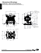
Dual Port (Aluminum Model Only) 1” NPT or 1” BSP Tapered EXTERNAL 1/2” NPT or 1/2” BSP Tapered INTERNAL (THIS PART REQUIRED FOR SINGLE PORT SUCTION ONLY) 1/2” NPT or 1/2” BSP Tapered INTERNAL (DUAL PORT PARTS ONLY) 1” NPT or 1” BSP Tapered EXTERNAL 1/2” NPT or 1/2” BSP Tapered INTERNAL (THIS PART REQUIRED FOR SINGLE PORT SUCTION ONLY) 1/2” NPT or 1/2” BSP Tapered INTERNAL (DUAL PORT PARTS ONLY) Illustration for Dual Port Suction and Single or Dual Port Discharge (Not available for Stainless Steel or Al
Written Warranty 5 - YEAR Limited Product Warranty Quality System ISO 9001 Certified • Environmental Management Systems ISO 14001 Certified Warren Rupp, Inc. (“Warren Rupp”) warrants to the original end-use purchaser that no product sold by Warren Rupp that bears a Warren Rupp brand shall fail under normal use and service due to a defect in material or workmanship within five years from the date of shipment from Warren Rupp’s factory.
EC Declaration of Conformity In accordance with ATEX Directive 94/9/EC, Equipment intended for use in potentially explosive environments. Manufacturer: Warren Rupp, Inc.®, A Unit of IDEX Corportion 800 North Main Street, P.O. Box 1568, Mansfield, OH 44902 USA EN 60079-25: 2011 For pumps equipped with Pulse Output ATEX Option Quality B.V.