
User Manual

SPI Protocol Definition
5-16 TriFlash with SD Interface Product Manual (Preliminary), Rev. 1.2 © 2002/2003 SANDISK CORPORATION
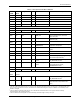
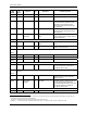
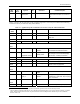
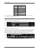
Table 5-4. SPI Bus Timing Diagrams
H Signal is high (logical ‘1’)
L Signal is low (logical ‘0’)
X Do not care
Z high impedance state (-> = 1)
* repeater
Busy Busy Token
Command Command token
Response Response token
Data block Data token
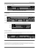
The host must keep the clock running for at least NCR clock cycles after the device response is received. This
restriction applied to command and data response tokens.
5.4.1. Command/Response
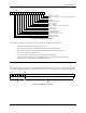
Host Command to Device Response—Device is Ready
CS
H H L L L * * * * * * * * * * * * * * * * * * * L L L L H H H
<-N
CS
-> <-N
EC
->
DataIN
X X H H H H 6 Bytes Command H H H H H * * * * * * * * * * * * * * * H H H H X X X
<-N
CR
->
DataOut
Z Z Z H H H H * * * * * * * * H H H H H 1 or 2 Bytes Response H H H H H Z Z
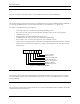
Figure 5-11. Host Command to Device Response Device is Ready
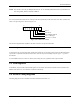
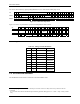
Host Command to Device Response—Device is Busy
The following timing diagram describes the command response transaction for commands when the device responds
with the R1b response type (e.g., SET_WRITE_PROT and ERASE). When the device is signaling busy, the host
may deselect it (by raising the CS) at any time. The device will release the DataOut line one clock after the CS
going high. To check if the device is still busy it needs to be reselected by asserting (set to low) the CS signal. The
device will resume busy signal (pulling DataOut low) one clock after the falling edge of CS.
CS
H L L L * * * * * * * * * * * * * * * * * * * L L L L H H H L L L L L L H H
<-N
CS
-> <-N
EC
-> <-N
DS
-> <-N
EC
->
DataIN
X H H H H 6 Bytes Command H H H H H H H H H H H H H X X X H H H H H H X X
<-N
CR
->
DataOut
Z Z H H H H * * * * * * * * H H H H Card Response Busy L Z Z Z Busy H H H H Z
Figure 5-12. Host Command to Device Response Device is Busy