
User Manual

SPI Protocol Definition
TriFlash with SD Interface Product Manual (Preliminary), Rev. 1.2 © 2002/2003 SANDISK CORPORATION
5-15
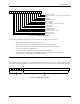
NOTE: This format is used only for Multiple Block Write. In case of Multiple Block Read the stop transmission is
done using STOP_TRAN Command (CMD12).
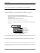
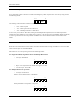
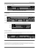
5.2.5. Data Error Token
If a read operation fails and the device cannot provide the required data it will send a data error token, instead. This
token is one byte long and is shown in Figure 5-10.
7
Error
CC Error
Card ECC Failed
Out of Range
Card is Locked
0
000
Figure 5-10. Data Error Token
The four least significant bits (LSB) are the same error bits as in response format R2.
5.2.6. Clearing Status Bits
As described in the previous paragraphs, in SPI mode, status bits are reported to the host in three different formats:
response R1, response R2 and data error token (the same bits may exist in multiple response types—e.g., Device
ECC failed).
As in the SD Bus mode, error bits are cleared when read by the host, regardless of the response format.
5.3. Card Registers
In SPI Mode, only the OCR, CSD and CID registers are accessible. Their format is identical to their format in the
SD Bus mode. However, a few fields are irrelevant in SPI mode.
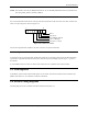
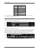
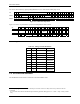
5.4. SPI Bus Timing Diagrams
All timing diagrams use the schematics and abbreviations listed in Table 5-4.