
User Manual

Secure Digital (SD) Bus Protocol Description
4-30 TriFlash with SD Interface Product Manual (Preliminary), Rev. 1.2 © 2002/2003 SANDISK CORPORATION
NOTE: The CRC response output is always two clocks after the end of data.
If the device does not have a free data receive buffer, the device indicates this condition by pulling down the data
line to LOW. The device stops pulling down the DAT0 line as soon as at least one receive buffer for the defined
data transfer block length becomes free. This signaling does not give any information about the data write status,
which must be polled by the host.
Multiple Block Write
In multiple block write mode, the device expects continuous flow of data blocks following the initial host write
command.
As in the case of single block write, the data is suffixed with CRC check bits to allow the device to check it for
transmission errors. The device sends back the CRC check result as a CRC status token on the DAT0 line. In the
case of transmission error the device sends a negative CRC status (‘101’). In the case of non-erroneous transmission
the device sends a positive CRC status (‘010’) and starts the data programming procedure. When a flash
programming error occurs the device will ignore all further data blocks. In this case no CRC response will be sent to
the host and, therefore, there will not be CRC start bit on the bus and the three CRC status bits will read (‘111‘).
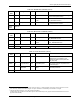
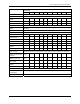
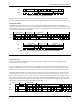
The data flow is terminated by a stop transmission command (CMD12). Figure 4-21 describes the timing of the data
blocks with and without device busy signal.
<-CardRsp->
CMD E Z Z P * * * * * * * * * * * * * * * P P P P P * * * * * * * * * * * * * * * P P P P P P P P P
<-N
WR
->
<-Write data->
CRC status <-N
WR
->
<-Write data->
CRC status <-Busy-> <-N
WR
->
DAT Z Z
P * P
S Data+CRC E
Z
Z S Status E Z
P * P
S Data+CRC E
Z
Z
S Status E S L*L E Z P*P
Figure 4-21. Timing of the Multiple Block Write Command
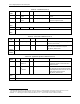
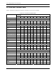
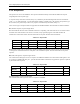
The stop transmission command works similar as in the read mode. Figure 4-22 to Figure 4-25 describe the timing
of the stop command in different device states.
<--Host Command--> <N
CX
Cycles>
<----Device response----> <Host Cmnd>
CMD S T content CRC E Z Z P P * * * * * * P S T content CRC E S T Content
<--------Device is programming--------->
DAT D D D D D D D D D D E Z Z S L * * * * * * * * * * * * * * * * * * * * * E Z Z Z Z Z Z Z Z
Figure 4-22. Stop Transmission During Data Transfer from the Host
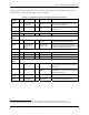
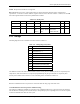
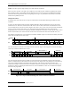
The card will treat a data block as successfully received and ready for programming only if the CRC data of the
block was validated and the CRC status token sent back to the host. Figure 4-23 is an example of an interrupted (by
a host stop command) attempt to transmit the CRC status block. The sequence is identical to all other stop
transmission examples. The end bit of the host command is followed, on the data line, with one more data bit, end
bit and two Z clock for switching the bus direction. The received data block, in this case is considered incomplete
and will not be programmed.
<--Host Command--> <-N
cr
Cycles->
<-----Card response-----> <Host Cmnd>
CMD S T content CRC E Z Z P P * * * * * * P S T content CRC E S T Content
<Data block> CRC Status
11
<--------Card is programming-------->
DAT D D D D D Z Z S Status E Z Z S L * * * * * * ** * * * * * * * * * * * * E Z Z Z Z Z Z Z Z
Figure 4-23. Stop Transmission During CRC Status Transfer from the Device
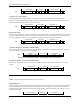
11
The card CRC status response was interrupted by the host.