
User Manual

Secure Digital (SD) Bus Protocol Description
4-26 TriFlash with SD Interface Product Manual (Preliminary), Rev. 1.2 © 2002/2003 SANDISK CORPORATION
4.10. Responses
All responses are sent via the CMD line. The response transmission always starts with the MSB. The response
length depends on the response type.
A response always starts with a start bit (always ‘0’), followed by the bit indicating the direction of transmission
(card = ‘0’). A value denoted by ‘x’ in the tables below indicates a variable entry. All responses except for the type
R3 (see below) are protected by a CRC. Every response is terminated by the end bit (always ‘1’).
There are four types of responses that are supported in the SanDisk TriFlash. Their formats are defined as follows:
R1 (standard response): response length 48 bit.
Bits 45:40 indicate the index of the command to which it is responding. The status of the device is coded in 32 bits.
Note that when a data transfer to the device is involved, a busy signal may appear on the data line after the
transmission of each block of data. The host will check for busy after the data block transmission.
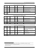
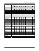
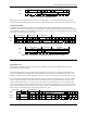
Table 4-13. Response R1
Bit Position 47 46 [45:40] [39:8] [7:1] 0
Width (bits) 1 1 6 32 7 1
Value ‘0’ ‘0’ x x x ‘1’
Description Start bit Transmission bit Command index Card status CRC7 End bit
R1b is identical to R1 with an optional busy signal transmitted on the data line. The device may become busy after
receiving these commands based on its state prior to the command reception. The host will check for busy at the
response.
R2 (CID, CSD register): response length 136 bits.
The content of the CID register is sent as a response to CMD2 and CMD10. The content of the CSD register is sent
as a response to CMD9. Only bits [127...1] of the CID and CSD are transferred, bit [0] of these registers is replaced
by the end bit of the response.
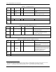
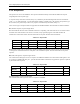
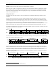
Table 4-14. Response R2
Bit Position 135 134 [133:128] [127:1] 0
Width (bits) 1 1 6 127 1
Value ‘0’ ‘0’ ‘111111’ x ‘1’
Description Start bit Transmission bit Reserved CID or CSD register incl. internal CRC7 End bit
R3 (OCR register): response length 48 bits.
The contents of the OCR register are sent as a response to ACMD41.
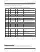
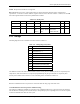
Table 4-15. Response R3
Bit Position 47 46 [45:40] [39:8] [7:1] 0
Width (bits) 1 1 6 32 7 1
Value ‘0’ ‘0’ ‘111111’ x ‘1111111’ ‘1’
Description Start bit Transmission bit Reserved OCR register Reserved End bit