
User Manual

Secure Digital (SD) Bus Protocol Description
TriFlash with SD Interface Product Manual (Preliminary), Rev. 1.2 © 2002/2003 SANDISK CORPORATION
4-5
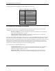
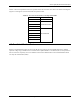
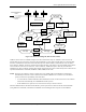
Table 4-2 shows the dependencies between operation modes and card states. Each state in the SD bus state diagrams
(Figure 4-7 and Figure 4-8) is associated with one operation mode.
Table 4-2. Overview of Card States versus Operation Modes
Card State Operation Mode
Inactive State Inactive
Idle State
Ready State Card Identification Mode
Identification State
Stand-by State
Transfer State
Sending-data State Data Transfer Mode
Receive-data State
Programming State
Disconnect State
4.3. Card Identification Mode
While in Card Identification Mode, the host resets all the devices that are in Card Identification Mode, validates
operation voltage range, identifies devices and asks them to publish Relative Card Address (RCA). This operation is
done to each device separately on its own CMD line. All the data communication in the Card Identification Mode
uses only the command line (CMD).