
User Manual

TriFlash Interface Description
3-22 TriFlash with SD Interface Product Manual (Preliminary), Rev. 1.2 © 2002/2003 SANDISK CORPORATION
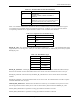
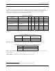
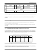
Table 3-26. SD Supported Security Algorithm
SD_SECURITY Supported Algorithm
0 No security
1 Security protocol 1.0
(Security Spec Ver 0.96)
2 Security protocol 2.0
(Security Spec Ver 1.0-1.01)
3 .. 7 Reserved
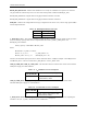
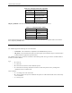
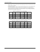
SD_BUS_WIDTHS—Describes all the DAT bus widths that are supported by this device.
Table 3-27. SD Supported Bus Widths
SD_BUS_WIDTHS Supported Bus Widths
Bit 0 1 bit (DAT0)
Bit 1 Reserved
Bit 2 4 bit (DAT0-3)
Bit 3 [MSB] Reserved
Since TriFlash shall support at least the two bus modes 1bit or 4bit width then any TriFlash shall set at least bits 0
and 2 (SD_BUS_WIDTH=0101).
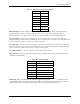
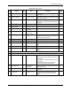
3.5.5. Status Register
The TriFlash supports the following two card status fields:
• Card Status—This status field is compatible to the MultiMediaCard protocol.
• SD_Status—This extended status field of 512 bits supports special features unique to the SD-interface
TriFlash and future application specific features.
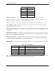
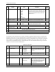
The TriFlash status registers’ structures are defined in the following tables. The Type and Clear-Condition fields in
the table are coded as follows:
Type:
• E—Error bit.
• S—Status bit.
• R—Detected and set for the actual command response.
• X—Detected and set during command execution. The host must poll the card by sending status
command in order to read these bits.
Clear Condition:
• A—According to the card current state.
• B—Always related to the previous command. Reception of a valid command will clear it (with a delay
of one command).
• C—Clear by read.