
User Manual

TriFlash Interface Description
TriFlash with SD Interface Product Manual (Preliminary), Rev. 1.2 © 2002/2003 SANDISK CORPORATION
3-7
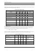
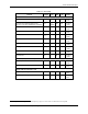
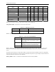
Logic working level
Supply voltage
Supply ramp up time
Bus master sup ply voltage
ACMD
V
DD
max
Valid voltage range
for commands
CMD0, 15, 55 and
ACMD41.
Valid voltage
range for all
other com-
mands and
memory access.
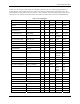
Power up time
Initialization delay:
The maximum of
CMD2
N
CC
N
CC
N
CC
1 msec, 74 clock cycles
and supply ramp up time.
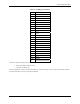
Initialization sequence
41
ACMD
41
ACMD
41
V
DD
min
time
Time out value for initialization process = 100 msec.
Optional repetitions of ACMD41
until no cards are responding
with busy bit set.
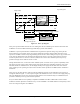
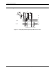
Figure 3-5. Power-up Diagram
After power up the TriFlash enters the idle state. During this state the TriFlash ignores all bus transactions until
ACMD41 is received (ACMD command type shall always precede with CMD55).
ACMD41 is a special synchronization command used to negotiate the operation voltage range and to poll the
devices until they are out of their power-up sequence. Besides the operation voltage profile of the devices, the
response to ACMD41 contains a busy flag, indicating that the device is still working on its power-up procedure and
is not ready for identification. This bit informs the host that the device is not ready. The host has to wait (and
continue to poll the devices, each one on his turn) until this bit is cleared. The maximum period of power up
procedure of single device shall not exceed 1 second.
Getting individual devices, as well as the whole TriFlash system, out of idle state is up to the responsibility of the
bus master. Since the power up time and the supply ramp up time depend on application parameters such as the
maximum number of TriFlash devices, the bus length and the power supply unit, the host must ensure that the
power is built up to the operating level (the same level which will be specified in ACMD41) before ACMD41 is
transmitted.
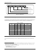
After power up, the host starts the clock and sends the initialising sequence on the CMD line. This sequence is a
contiguous stream of logical ‘1’s. The sequence length is the maximum of 1msec, 74 clocks or the supply-ramp-up-
time. The additional 10 clocks (over the 64 clocks after what the device should be ready for communication) are
provided to eliminate power-up synchronization problems.
Every bus master shall have the capability to implement ACMD41 and CMD1. CMD1 will be used to ask the
TriFlash to send their Operation Conditions. In any case the ACMD41 or the CMD1 shall be send separately to each
device accessing it through its own CMD line.