
User Manual

TriFlash Interface Description
3-4 TriFlash with SD Interface Product Manual (Preliminary), Rev. 1.2 © 2002/2003 SANDISK CORPORATION
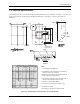
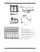
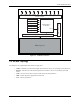
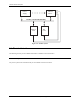
Figure 3-2 shows the bus topology of several devices with one host in SD Bus mode.
Figure 3-2. TriFlash System Bus Topology
During the initialization process, commands are sent to each device individually, allowing the application to detect
the devices and assign logical addresses to the physical slots. Data is always sent to each device individually.
However, to simplify the handling of the card stack, after initialization, all commands may be sent concurrently to
all devices. Addressing information is provided in the command packet.
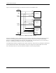
The SD Bus allows dynamic configuration of the number of data lines. After power-up, by default, the TriFlash will
use only DAT0 for data transfer. After initialization, the host can change the bus width (number of active data
lines). This feature allows an easy trade off between hardware cost and system performance.
TriFlash (A)
CLK
Vdd
Vss
D0-D3, CMD
SD Memory
Card (B)
CLK
Vdd
Vss
D0-D3, CMD
MultiMediaCard
(C)
CLK
Vdd
Vss
D0, CS, CMD
CLK
Vdd
Vss
D0-3(A),
CMD(A)
D0-3(B),
CMD(B)
D0-3(C)
CMD(C)
HOST
D1&D2 Not
Connected