
Product manual

Preliminary CompactFlash Memory Card Product Manual
SanDisk CompactFlash Memory Card Product Manual Rev. 8 © 2001 SANDISK CORPORATION
25
4.3 Electrical Specification
The following table defines all D.C. Characteristics
for the CompactFlash Memory Card Series.
Unless otherwise stated, conditions are:
SDCFB-XX SDCFBI-XX
Vcc = 5V ±10% Vcc = 5V ± 10%
Vcc = 3.3V ± 5% Vcc = 3.3V ± 5%
Ta = 0°C to 60°C Ta = -40°C to 85°C
Absolute Maximum conditions are:
Vcc = -0.3V min. to 7.0V max.
V* = -0.5V min. to Vcc + 0.5V max.
* Voltage on any pin except Vcc with respect to GND.
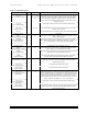
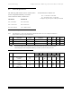
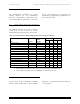
4.3.1 Input Leakage Control
Note: In the table below, x refers to the characteristics described in section 4.3.2. For example, I1U indicates a
pull up resistor with a type 1 input characteristic.
Type Parameter Symbol Conditions MIN TYP MAX Units
IxZ Input Leakage Current IL Vih = Vcc / Vil = Gnd -1 1 µA
IxU Pull Up Resistor RPU1 Vcc = 5.0V 50k 500k Ohm
IxD Pull Down Resistor RPD1 Vcc = 5.0V 50k 500k Ohm
Note: The minimum pullup resistor leakage current meets the PCMCIA specification of 10k ohms but is
intentionally higher in the CompactFlash Memory Card Series product to reduce power use.
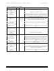
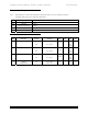
4.3.2 Input Characteristics
Type Parameter Symbol MIN TYP MAX MIN TYP MAX Units
VCC = 3.3 V VCC = 5.0 V
1 Input Voltage
CMOS
Vih
Vil
2.4
0.6
2.4
0.8
Volts
2 Input Voltage
CMOS
Vih
Vil
1.5
0.6
2.0
0.8
Volts
3 Input Voltage
CMOS
Schmitt Trigger
Vth
Vtl
1.8
1.0
2.8
2.0
Volts