
Product manual

CompactFlash Memory Card Product Manual Preliminary
SanDisk CompactFlash Memory Card Product Manual Rev. 8 © 2001 SANDISK CORPORATION
24
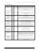
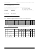
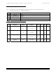
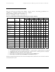
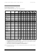
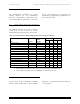
Table 4-2 Signal Description (continued)
Signal Name Dir. Pin Description
RESET
(PC Card Memory Mode)
I 41 When the pin is high, this signal resets the CompactFlash Card. The
card is Reset only at power up if this pin is left high or open from
power-up. The card is also reset when the Soft Reset bit in the Card
Configuration Option Register is set.
RESET
(PC Card I/O Mode)
This signal is the same as the PC Card Memory Mode signal.
-RESET
(True IDE Mode)
In the True IDE Mode this input pin is the active low hardware reset
from the host.
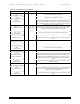
VCC
(PC Card Memory Mode)
-- 13, 38 +5 V, +3.3 V power.
VCC
(PC Card I/O Mode)
This signal is the same for all modes.
VCC
(True IDE Mode)
This signal is the same for all modes.
-VS1
-VS2
(PC Card Memory Mode)
O 33
40
Voltage Sense Signals. -VS1 is grounded so that the CompactFlash
Card CIS can be read at 3.3 volts and -VS2 is open and reserved by
PCMCIA for a secondary voltage.
-VS1
-VS2
(PC Card I/O Mode)
This signal is the same for all modes.
-VS1
-VS2
(True IDE Mode)
This signal is the same for all modes.
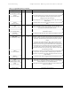
-WAIT
(PC Card Memory Mode)
O 42 The -WAIT signal is driven low by the CompactFlash Card to signal
the host to delay completion of a memory or I/O cycle that is in
progress.
-WAIT
(PC Card I/O Mode)
This signal is the same as the PC Card Memory Mode signal.
IORDY
(True IDE Mode)
In True IDE Mode this output signal may be used as IORDY.
-WE
(PC Card Memory Mode)
I 36 This is a signal driven by the host and used for strobing memory write
data to the registers of the CompactFlash Card when the card is
configured in the memory interface mode. It is also used for writing
the configuration registers.
-WE
(PC Card I/O Mode)
In PC Card I/O Mode, this signal is used for writing the configuration
registers.
-WE
(True IDE Mode)
In True IDE Mode this input signal is not used and should be
connected to VCC by the host.
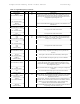
WP
(PC Card Memory Mode)
Write Protect
O 24 Memory Mode - The CompactFlash Card does not have a write protect
switch. This signal is held low after the completion of the reset
initialization sequence.
-IOIS16
( PC Card I/O Mode)
I/O Operation - When the CompactFlash Card is configured for I/O
Operation, Pin 24 is used for the -I/O Selected is 16 Bit Port (-IOIS16)
function. A Low signal indicates that a 16 bit or odd byte only
operation can be performed at the addressed port.
-IOCS16
(True IDE Mode)
In True IDE Mode this output signal is asserted low when this device
is expecting a word data transfer cycle.