
User Manual

SanDisk CompactFlash Card OEM Product Manual Interface Description
02/09, Rev. 1.0 ii © 2007 - 2009 SanDisk Corporation. SanDisk Confidential, subject to all applicable non-disclosure agreements.
23
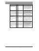
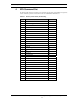
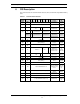
Table 3-6 defines the input characteristics of the parameters in Table 3-5.
Table 3-6 Input Characteristics
Min. Typ. Max. Min. Typ. Max.
Type Parameter Symbol
VCC=3.3V VCC=5.0V
Unit
1 Input Voltage
CMOS
Vih
Vil
2.0
0.8
2.0
0.8
Volts
2 Input Voltage
CMOS
Vih
Vil
2.0
0.8
2.0
0.8
Volts
3 Input Voltage
CMOS
Schmitt Trigger
Vt+(Vp)
1
Vt-(Vn)
2
Vh(ΔVt)
3
0.9
0.7
0.2
2.1
1.9
1.4
0.9
0.7
0.2
2.1
1.9
1.4
Volts
Notes:
1) Vt+(Vp) is the positive going threshold voltage.
2) Vt-(Vn) is the negative going threshold voltage.
3) Vh(ΔVt) is the hysteresis voltage
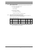
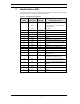
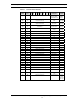
In UDMA modes greater than 4, the following characteristics apply. Voltage output high and
low values shall be met at the source connector to include the effect of series termination.
Table 3-7 Input Characteristics (UDMA Mode > 4)
Parameter Symbol MIN MAX Units
DC supply voltage to receivers V
DD3
3.3 - 8% 3.3 + 8% Volts
Low to high input threshold V+ 1.5 2.0 Volts
High to low input threshold
V−
1.0 1.5 Volts
Difference between input thresholds:
((V+
current value
) − (V−
current value
))
V
HYS
320 mV
Average of thresholds: ((V+
current value
) +
(V−
current value
))/2
V
THRAVG
1.3 1.7 Volts
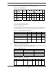
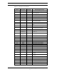
3.3.2 Output Drive Type and Characteristics
In Table 3-8 "x" refers to the characteristics described in Table 3-8. For example–"OT3" refers
to Totempole output with a Type 3 output drive characteristic.
Table 3-8 Output Drive Type
Type Output Type Valid Conditions
OTx Totempole loh & lol
OZx Tri-state N-P Channel loh & lol
OPx P-Channel Only loh only
ONx N-Channel Only loh Only
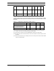
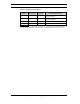
Table 3-9 Output Drive Characteristics
Type Parameter Symbol Conditions Min. Typ. Max. Unit
1 Output Voltage Voh
Vol
Ioh = -4 mA
Iol = 4 mA
2.4V
0.4V
Volts