
User Manual


SanDisk CompactFlash Card OEM Product Manual Interface Description
02/09, Rev. 1.0 ii © 2007 - 2009 SanDisk Corporation. SanDisk Confidential, subject to all applicable non-disclosure agreements.
18
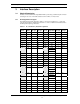
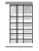
Signal Name Dir. Pin Description
-HDMARDY
(All Modes - Ultra DMA
Protocol DMA Read)
In all modes when Ultra DMA mode DMA
Read is active, this signal is asserted by
the host to indicate that the host is ready
to receive Ultra DMA data-in bursts. The
host may negate –HDMARDY to pause an
Ultra DMA transfer.
HSTROBE
(All Modes - Ultra DMA
Protocol DMA Write)
In all modes when Ultra DMA mode DMA
Write is active, this signal is the data out
strobe generated by the host. Both the
rising and falling edge of HSTROBE
cause data to be latched by the device.
The host may stop generating HSTROBE
edges to pause an Ultra DMA data-out
burst.
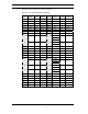
-IOWR
(PC Card Memory Mode –
Except Ultra DMA
Protocol Active)
I 35 This signal is not used in this mode.
-IOWR
(PC Card I/O Mode –
Except Ultra DMA
Protocol Active)
The I/O Write strobe pulse is used to clock
I/O data on the Card Data bus into the
CompactFlash Storage Card or CF+ Card
controller registers when the
CompactFlash Storage Card or CF+ Card
is configured to use the I/O interface.
The clocking shall occur on the negative
to positive edge of the signal (trailing
edge).
-IOWR
(True IDE Mode – Except
Ultra DMA Protocol
Active)
In True IDE Mode, while Ultra DMA mode
protocol is not active, this signal has the
same function as in PC Card I/O Mode.
When Ultra DMA mode protocol is
supported, this signal must be negated
before entering Ultra DMA mode protocol.
STOP
(All Modes – Ultra DMA
Protocol Active)
In All Modes, while Ultra DMA mode
protocol is active, the assertion of this
signal causes the termination of the Ultra
DMA data burst.
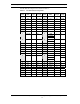
-OE
(PC Card Memory Mode)
I 9 This is an Output Enable strobe generated
by the host interface. It is used to read
data from the CompactFlash Storage Card
or CF+ Card in Memory Mode and to read
the CIS and configuration registers.
-OE
(PC Card I/O Mode)
In PC Card I/O Mode, this signal is used
to read the CIS and configuration
registers.
-ATA SEL
(True IDE Mode)
To enable True IDE Mode this input
should be grounded by the host.