
User Manual


CompactFlash
®
Memory Card Product Manual, Rev. 10.0 © 2002 SANDISK CORPORATION 4-1
4. ATA Drive Register Set Definition and Protocol
The CompactFlash Memory Card can be configured as a high performance I/O device through the following ways:
•
Standard PC-AT disk I/O address spaces 1F0h-1F7h, 3F6h-3F7h (primary); 170h-177h, 376h-377h
(secondary) with IRQ 14 (or other available IRQ).
•
Any system decoded 16-byte I/O block using any available IRQ.
•
Memory space.
The communication to or from the CompactFlash Memory Card is done using the Task File registers, which provide
all the necessary registers for control and status information. The PCMCIA interface connects peripherals to the host
using four register mapping methods. Table 4-1 is a detailed description of these methods.
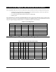
Table 4-1. I/O Configurations
Standard Configurations
Config Index IO or Memory Address Drive # Description
0 Memory 0-F, 400-7FF 0 Memory Mapped
1 I/O XX0-XXF 0 I/O Mapped 16 Contiguous Registers
2 I/O 1F0-1F7, 3F6-3F7 0 Primary I/O Mapped Drive 0
2 I/O 1F0-1F7, 3F6-3F7 1 Primary I/O Mapped Drive 1
3 I/O 170-177, 376-377 0 Secondary I/O Mapped Drive 0
3 I/O 170-177, 376-377 1 Secondary I/O Mapped Drive 1
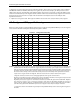
4.1. I/O Primary and Secondary Address Configurations
Table 4-2. Primary and Secondary I/O Decoding
-REG A9-A4 A3 A2 A1 A0 -IORD=0 -IOWR=0 Note
0 1F(17) 0 0 0 0 Even RD Data Even WR Data 1, 2
0 1F(17) 0 0 0 1 Error Register Features 1
0 1F(17) 0 0 1 0 Sector Count Sector Count
0 1F(17) 0 0 1 1 Sector No. Sector No.
0 1F(17) 0 1 0 0 Cylinder Low Cylinder Low
0 1F(17) 0 1 0 1 Cylinder High Cylinder High
0 1F(17) 0 1 1 0 Select Card/Head Select Card/Head
0 1F(17) 0 1 1 1 Status Command
0 3F(37) 0 1 1 0 Alt Status Device Control
0 3F(37) 0 1 1 1 Drive Address Reserved