
User Manual


CompactFlash Memory Card Interface Description
CompactFlash
®
Memory Card Product Manual, Rev. 10.0 © 2002 SANDISK CORPORATION 3-7
3.3.1. Input Leakage Control
NOTE: In Table 3-3 x refers to the characteristics described in Section 3.3.2. For example, I1U indicates a pull up
resistor with a type 1 input characteristic.
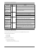
Table 3-3. Input Leakage Control
Type Parameter Symbol Conditions MIN TYP MAX Units
IxZ Input Leakage Current IL Vih = Vcc/Vil = Gnd -1 1 µA
IxU Pull Up Resistor RPU1 Vcc = 5.0V 50k 500k Ohm
IxD Pull Down Resistor RPD1 Vcc = 5.0V 50k 500k Ohm
NOTE: The minimum pullup resistor leakage current meets the PCMCIA specification of 10k ohms but is
intentionally higher in the CompactFlash Memory Card Series product to reduce power use.
3.3.2. Input Characteristics
Table 3-4. Input Characteristics
MIN TYP MAX MIN TYP MAX Type Parameter Symbol
VCC = 3.3 V VCC = 5.0 V
Units
1 Input Voltage
CMOS
Vih
Vil
2.4
0.6
2.4
0.8
Volts
2 Input Voltage
CMOS
Vih
Vil
1.5
0.6
2.0
0.8
Volts
3 Input Voltage
CMOS
Schmitt Trigger
Vth
Vtl
1.8
1.0
2.8
2.0
Volts
3.3.3. Output Drive Type
In Table 3-5 x refers to the characteristics described in Section 3.3.4. For example, OT3 refers to Totempole output
with a type 3 output drive characteristic.
Table 3-5. Output Drive Type
Type Output Type Valid Conditions
OTx Totempole Ioh & Iol
OZx Tri-State N-P Channel Ioh & Iol
OPx P-Channel Only Ioh Only
ONx N-Channel Only Iol Only