
User Manual


CompactFlash Memory Card Interface Description
3-4 CompactFlash
®
Memory Card Product Manual, Rev. 10.0 © 2002 SANDISK CORPORATION
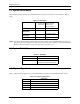
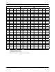
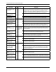
Signal Name Dir. Pin Description
-CE1, -CE2
(PC Card Memory Mode)
Card Enable
I 7, 32
These input signals are used both to select the card and to indicate to the card
whether a byte or a word operation is being performed. -CE2 always accesses the
odd byte of the word. -CE1 accesses the even byte or the Odd byte of the word
depending on A0 and -CE2. A multiplexing scheme based on A0, -CE1, -CE2 allows 8
bit hosts to access all data on D0 -D7. See Tables 3-11, 3-12, 3-15, and 3-16.
-CE1, -CE2
(PC Card I/O Mode)
Card Enable
This signal is the same as the PC Card Memory Mode signal.
-CS0, -CS1
(True IDE Mode)
In the True IDE Mode -CS0 is the chip select for the task file registers while -CS1 is
used to select the Alternate Status Register and the Device Control Register.
-CSEL
(PC Card Memory Mode)
I 39 This signal is not used for this mode.
-CSEL
(PC Card I/O Mode)
This signal is not used for this mode.
-CSEL
(True IDE Mode)
This internally pulled up signal is used to configure this device as a Master or a Slave
when configured in the True IDE Mode. When this pin is grounded, this device is
configured as a Master. When the pin is open, this device is conf igured as a Slave.
D15—D00
(PC Card Memory Mode)
I/O
31, 30, 29, 28,
27, 49, 48, 47,
6, 5, 4, 3, 2, 23,
22, 21
These lines carry the Data, Commands and Status information between the host and
the controller. D00 is the LSB of the Even Byte of the Word. D0 8 is the LSB of the
Odd Byte of the Word.
D15—D00
(PC Card I/O Mode)
These signals are the same as the PC Card Memory Mode signal.
D15—D00
(True IDE Mode)
In True IDE Mode all Task File operations occur in byte mode on the low order bus
D00-D07 while all data transfers are 16 bits using D00-D15.
GND
(PC Card Memory Mode)
-- 1, 50 Ground.
GND
(PC Card I/O Mode)
This signal is the same for all modes.
GND
(True IDE Mode)
This signal is the same for all modes.
-INPACK
( PC Card Memory Mode)
O 43 This signal is not used in this mode.
-INPACK
( PC Card I/O Mode)
Input Acknowledge
The Input Acknowledge signal is asserted by the CompactFlash Card when the card is
selected and responding to an I/O read cycle at the address that is on the address
bus. This signal is used by the host to control the enable of any input data buffers
between the card and the CPU.
-INPACK
(True IDE Mode)
In True IDE Mode this output signal is not used and should not be connected at the
host.
-IORD
(PC Card Memory Mode)
I 34 This signal is not used in this mode.
-IORD
(PC Card I/O Mode)
This is an I/O Read strobe generated by the host. This signal gates I/O data onto the
bus from the CompactFlash Card when the card is configured to use the I/O interface.
-IORD
(True IDE Mode)
In True IDE Mode, this signal has the same function as in PC Card I/O Mode.