SanDisk SD-ROM Product Manual Revision 1.0 SanDisk Corporation Corporate Headquarters . 601 McCarthy Boulevard . Milpitas, California 95035 Phone: 408-801-1000 . Fax: 408-801-8657 www.sandisk.
SanDisk® Corporation general policy does not recommend the use of its products in life support applications where in a failure or malfunction of the product may directly threaten life or injury. Per SanDisk Terms and Conditions of Sale, the user of SanDisk products in life support applications assumes all risk of such use and indemnifies SanDisk against all damages. See "Disclaimer of Liability." This document is for information use only and is subject to change without prior notice.
1 SD-ROM Card Overview 1.1 Introduction SanDisk SD-ROM Cards provide permanent and secure read-only data storage for consumer electronic and personal computer applications. SanDisk SD-ROM Cards are based on SanDisk’s unique 3D one-time programmable (OTP) memory devices which safely store data for 100 years. This compares favorably with cards based on flash memory devices, which are typically rated to store data for 10 years or less.
2 SanDisk SD-ROM Card Functional Description SanDisk SD-ROM Cards are compatible with the SD specifications, with some changes necessary for a read-only memory. In an SD host system, the host controls all communication between itself and the cards. For detailed information, refer to Section 4 of the SDA Physical Layer Specification, Version 2.00. This chapter contains the functional description for SanDisk SD-ROM Cards. 2.
2.7 Card State Transitions SanDisk SD-ROM Cards operate the same as standard SD cards, where the state transition is dependent on the received command along with responses sent on the command line. The transitions are defined in Section 4.8 of the SDA Physical Layer Specification, Version 2.00 In Card Identification Mode, the host operates the card at a slower frequency as it identifies and initializes the card. For more information see Section 4.2 in the SDA Physical Layer Specification, Version 2.00.
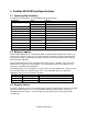
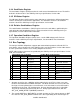
3 SanDisk SD-ROM Card Specifications 3.1 Operating Specifications The table below summarizes the SD-ROM operating specifications. Parameter Supply Voltage Value 2.0 – 3.6v 2.7 – 3.6v Notes during card identification for version 1.1 cards all supported commands Operating Temperature Storage Temperature Data Retention Data Endurance Interface speed Read Bandwidth -25 – 85 °C -40 – 85 °C 100 years minimum 1x10⁹ read cycles 0 – 25MHz 1.
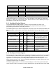
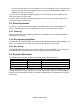
Register Abbreviation CID CSD SCR RCA OCR SSR CSR Width (in bits) 128 128 64 16 32 512 32 Register Name Card IDentification Card-Specific Data SD Configuration Register Relative Card Address Operation Condition Register SD Status Register Card Status Register All card registers are also accessible in SPI Mode. Their format is identical to the format in the SD Bus Mode; however, a few fields are not used in SPI Mode. In SPI Mode, the Card Status Register has a different, shorter format as well.
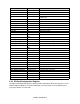
Field CSD_STRUCTURE Reserved TAAC Value 1.0 NSAC 0 TRANS_SPEED CCC READ_BL_LEN READ_BL_PARTIAL WRITE_BLK_MISALIGN READ_BLK_MISALIGN DSR_IMP Reserved C_SIZE 25MHz 0x5F5 512 bytes Yes No No No VDD_R_CURR_MIN VDD_R_CURR_MAX VDD_W_CURR_MIN VDD_W_CURR_MAX C_SIZE_MULT ERASE_BLK_EN SECTOR_SIZE WP_GRP_SIZE WP_GRP_ENABLE Reserved R2W_FACTOR WRITE_BL_LEN WRITE_BL_PARTIAL FILE_FORMAT_GRP COPY PERM_WRITE_PROTECT TMP_WRITE_PROTECT FILE_FORMAT Reserved CRC 1.
3.3.4 Card Status Register The Card Status Register (CSR) transmits the card's status information to the host. The CSR is defined in Section 4.10.1 in the SDA Physical Layer Specification, Version 2.00. 3.3.5 SD Status Register The SD Status Register (SSR) contains status bits that are related to the SD Card proprietary features and may be used for future applications. The SD Status structure is described in Section 4.10.2 in the SDA Physical Layer Specification, Version 2.00. 3.3.
connect external pullup resistors to all data lines even if only DAT0 is to be used. Otherwise, non-expected high current consumption may occur due to the floating inputs of DAT1 and DAT2 (in case they are not used). For more details regarding the SD Bus topology, refer to Section 3.5.1 of the SDA Physical Layer Specification, Version 2.00. For more details regarding the SPI Bus topology, refer to Section 3.5.2 of the SDA Physical Layer Specification, Version 2.00. 3.
SanDisk Confidential