TEMI880 - Color type TEMI850 - Mono type INSTRUCTION MANUAL TEMPERATURE • HUMIDITY PROGRAMMABLE CONTROLLER
SAMWONTECH Contents 1 Installation Manual 1.1 1.2 1.3 1.4 Introductions ………………………………………………………………………………… Package checklist ………………………………………………………………………………… Installation ……………………………………………………………………………………………………… Wiring …………………………………………………………………………………………………………… 1 3 5 9 2 User Manual 2.1 2.2 2.3 2.4 2.5 2.
SAMWONTECH ※ This manual is used for the common use of the TEMI880 and TEMI850(Marking is only used TEMI880). 1. Installation Manual 1.1 Introductions Thank you for purchasing our Industrial Controller. This manual explains suitable effective way of using and installing this product. 음SYMBOL MARK음 (1) This symbol is used for danger or warning. (A) Product : Indicates an imminently hazardous situation which If not avoided, will result in serious injury or out of order.
SAMWONTECH Regarding Protection, Safety and Prohibition (1) In the interest of protecting and ensuring the safety of this product and the system, which is controlled by this product, ensure that all instructions and precautions and precautions in this manual relating to safety are strictly adhered to in the use of this product. (2) Take note that if you handle the product in contradiction to these instructions, we does not guarantee safety.
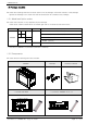
SAMWONTECH 1.2 Package checklist ▶ Check the following when the controller opens from its package. Check the contents of the package against the Package List to make sure that all accessories are included in the package. 1.2.1 Model and Option codes ▶ Check the controller for any apparent physical damage. Check point : Model number which is located right side of controller and left side of box.
SAMWONTECH 1.2.3 Missed or damaged items ▶ If any of these items are missed or damaged, please contact your agent or sales representative for assistance. Lifetime of the parts in the controller ▶ Check the lifetime for parts and we strongly recommend replace it if the lifetime is finished. ■ ■ ■ ■ FUSE BACKLIGHT RELAY BATTERY SR-5:630mA/250VAC JQ1P-DC24V ER3VT(3.
SAMWONTECH 1.3 Installation 1.3.1 Location and Environment 음Important (1) NEVER touch the terminals or else you will get an electrical shock, if the unit is power-on. (2) To install the controller, select a location where : ■ No one may accidentally touch the terminals. ■ Mechanical vibrations are minimal. ■ Corrosive gas is minimal. ■ Temperature can be maintained between 10℃ to 50℃ and fluctuation is minimal. ■ Indoor use only. ■ Altitude is up to 2,000m.
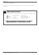
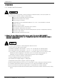
SAMWONTECH 1.3.3 External and Panel Cutout Dimensions 1.3.4 PANEL CUTTING 1 ○ Normal Adhesion 3rd Edition of TEMI880 IM : Aug. 22.
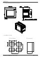
SAMWONTECH 1.3.5 Installation (Mount) PANEL Mount Screwdriver Insert ( ) : inch Panel Thickness: 1 (0.04) ~ 10 (0.39) mm 1 ○ 2 ○ 3 ○ Cut the mounting panel as Section.( See 1.3.4. PANEL CUTTING) Insert the unit from its back terminal board side. Attach the left and right brackets to the unit to fix the unit to the mounting panel. (use screwdriver) CAUTION(Mount) ▶ Do not tighten the mounting screw excessively, the unit case or bracket may be damaged. 3rd Edition of TEMI880 IM : Aug. 22.
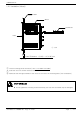
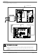
SAMWONTECH 1.3.6 Installation (Wiring for ground) Chamber Case Circuit Breaker ~ ○ ● N1 N2 ● ● L1 L2 ● ● G1 G2 ● Relay Contact Output SSR/SCR, Recorder (Transmission Output) Contact Input : DI CAUTION(Wiring for ground) ▶ Make sure ground with Temp. and Humi. chamber case when install power injection. ▶ Make sure wiring of ground power source with circuit breaker in the Temp. & Humi. chamber. ▶ Make sure wiring of ground with controller circuit breaker in Temp. & Humi. chamber.
SAMWONTECH 1.4 Wiring CAUTION (Wiring) ▶ Before carrying out wiring, turn off the power to the controller and check that the cables to be connected are not alive with a tester or the like because there is a possibility of electric shock. Person who have basic electrical knowledge and practical experience must carry out wiring. ▶ The controller must be wired directly from circuit breaker output on inside of temperature & humidity chamber for avoid damage of controller or temperature & humidity chamber. 1.
SAMWONTECH 1.4.2 Terminal wiring diagram 1.4.2.1 TEMI880 Body Terminal OPTION1 : TEMI880-11(RS485 + I/O1) RTX+ RTX- SG 5 8 4 S R STANDARD : TEMI880-10(RS232C + I/O1) 2 3 2 S R Additional UDC Option : TEMI880-10/UDC Additional UDC Option : TEMI880-11/UDC OPTION2 : TEMI880-20(RS232C + I/O1 + I/O2) OPTION3 : TEMI880-21(RS485 + I/O1 + 1/O2) K N I L 2 O / I 5 8 4 S R K N I L 2 O / I 2 3 2 S R 3rd Edition of TEMI880 IM : Aug. 22.
SAMWONTECH 1.4.2.2 I/O1 RELAY BOARD RLY7_NC RLY7_NO COM4 RLY8_NC RLY8_NO RLY9_NC RLY9_NO COM5 RLY10_NC RLY10_NO External relay switch → It is operated with RLY 10 on the “AND” condition. AOUT1- AOUT1+ Temp. control output AOUT2- AOUT2+ Humi. control output RET1- RET1+ Temp. transmission output RET2- RET2+ Humi. transmission output RLY6 P10 COM3 RLY5 I/O1 BOARD RLY4 COM2 I/O1 LINK RLY3 RLY2 COM1 RLY1 L N FG 220VAC +24V GND DI_COM DI_COM DI8 DI7 DI6 DI5 DI4 DI3 DI2 DI1 1.4.2.
SAMWONTECH 1.4.2.4 Grounding and Power Wiring ▶ Use a cable 2 ㎟ or more thick for grounding with class 3 grounding(grounding resistance a 100Ω or less) or higher. Do not extend the grounding cable over 20m. ▶ Ground from the ground terminal with a one-point contact. Do not wire between ground terminals. ▶ Use appropriate cables equivalent to vinyl insulation cable(KSC 3304) or more. L 100~240V AC 50/60Hz N FG Class 3 Ground Ground FRAME GROUND(FG) Exactly. 1.4.2.
SAMWONTECH 1.4.2.6 Control Output and Transmission Output Wiring CAUTION ▶ Before starting control output and transmission output wiring, be sure to turn off the system, or else you will get an electrical shock. ▶ When connecting, do not mix up the input polarity, Connecting with the wrong polarity can cause serious accidents. ▶ For input wiring, use a shielded cable. Ground the shield at one point. Temp. Control Output Wiring(SSR/4~20mA) Humi.
SAMWONTECH 1.4.2.7 External Contact Output(RELAY) Wiring CAUTION ▶ Before carrying out wiring, turn off the power to the controller and check that the cables to be connected are not alive with a tester because there is a possibility of electric shock.
SAMWONTECH 1.4.2.8 External Contact Input : DI CAUTION ▶ Before starting external contact output : DI wiring, be sure to turn off the system, or else you will get an electrical shock. ▶ For the external contact, use a no-voltage contact(including relay contact) that can operate appropriately under the terminal voltage for a close contact(approximate.. 5V) and the current for a opened contact(approximate.. 1mA).
SAMWONTECH 1.4.2.9 Auxiliary Relay CAUTION ▶ If contact capacity is over 250VAC – resistance load 5A, 30VDC – resistance load 5A, use auxiliary relay for ON/OFF load. ▶ If you INDUCTANCE(L) load like as AUXILIARY RELAY or SOLENOIDE VALVE, It might make go to wrong or out of order relay, please make sure insert to parallel circuit with CR FILTER(AC) or DIODE(DC) by SURGE SUPPRESSOR of avoiding sparks. ▶ Recommend CR FILTER → Sung Ho Electronics : BSE104R120 25V (0.1μ+120Ω) → HANA PARTS CO.
SAMWONTECH 1.4.2.10 Communication(RS485/RS232C) Wiring CAUTION ▶ Before starting communication wiring, be sure to turn off the system, or else you will get an electrical shock. 1.4.2.10.1 RS485 Wiring ▶ The slave side(TEMI880) can accommodate up to 99 units in a MULTIDROP connection. ▶ Be sure to connect a terminating resistance(220Ω 1/4W) to the units at the both.
SAMWONTECH 2. User Manual 2.1 Setup Button ▶ TEMI880 is easy to install & modify by touch screen as well as the map type menu. User enables to grasp the operation of control system with easy through graph on vivid LCD screen. 2.1.1 Initial setup button ▶ Display of the general setting button. Table 1-1. General Setting Button Button Function Change the page. 1 Main 2 General execute button It is used general execution or selection.
SAMWONTECH 3 ○ Input key for the Time Signal setting Touch Key Unlock ▶ If KEY LOCK is ON, Not input setting value. Therefore, Input setting value after KEY LOCK ▶ convert OFF. ☞ For more information, See 2.7 Operation Setting Screen. 2.1.3 Input error ▶ User can check a number of buzzer times. ☞ 1 time : Succeed set the data ☞ 3 times : Failed set the data Using the touch screen ▶ Please do not use any pen/pencil, nail or any other sharp material.
SAMWONTECH 2.2 Input Setting Value ▶ All of the Input value is setting by use setting value, pattern name and time signal input key. ▶ If user push setting value input button in the Table 1-1(General Setting Button), User can input data value. ▶ For the Time Signal input key, See 2.10.4 Time Signal Setting Screen. ▶ For the Pattern Name input key, See 2.10.6 Pattern Name Setting Screen. 2.2.
SAMWONTECH 2.3 Block diagram of the basic processing Power On [PROG STOP] [Initial Screen] [FIX STOP] [Main Screen] [DI TROUBLE SCREEN] [PROGRAM SET] [SYSTEM SETUP] [SETUP PASSWORD] 3rd Edition of TEMI880 IM : Aug. 22.
SAMWONTECH 2.4 Initial Screen ▶ Initial Screen(the Beginning Power On). ▶ After 3 seconds, Transfer 2.6.1 Program Stop Screen automatically. Figure 2-1. Initial Screen 1 ○ 2 ○ 3 ○ 4 ○ No. Contents Description 1 ○ Version 2 ○ Company Display company name. 3 ○ Telephone Display telephone number. 4 ○ Homepage Display homepage address. Display present version information. 3rd Edition of TEMI880 IM : Aug. 22. 2005 Additional Description ▶ V1R0 → VERSION 1, REVISION 0 ▶ Modify at 2.12.
SAMWONTECH 2.5 Main Screen ▶ This screen is center of the total screen transfer. 7 ` ○ Figure 2-2. Main Screen A ○ B ○ 1 ○ 4 ○ 2 ○ 5 ○ 3 ○ 6 ○ No. Contents 1 ○ Operation Screen 2 ○ Description Additional Description Transfer operation screen. ▶ See 2.6 Operation Screen Set Function Transfer function and FIX setting screen. ▶ See 2.7 Operation Setting Screen 3 ○ Set Reserve Transfer reserve setting screen. ▶ See 2.
SAMWONTECH 2.6 Operation Screen ▶ At the running TEMI880, Display status and information. 2.6.1 Program Stop Screen Figure 2-3. PROG STOP Screen 8 ○ 1 ○ 2 ○ 4 ○ 3 ○ 5 ○ 6 ○ 7 ○ No. Contents Description 1 ○ Main Button Transfer to 2.5 Main Screen. 2 ○ Present Temp. Display present temperature. 3 ○ Present Humi. Display present humidity. 4 ○ Pattern No. 5 ○ Segment Additional Description ▶ Proper sensor type is in need of setting at 2.12.
SAMWONTECH Figure 2-4. PROG STOP – Confirm Figure 2-5. PROG STOP – Pattern End 1 ○ 2 ○ Figure 2-6. PROG STOP – Reserved 3 ○ 5 ○ 4 ○ No. Contents 1 ○ Confirmable Box 2 ○ Pattern End 3 ○ Start Time 4 ○ Reservation 5 ○ Cancel Button Description Additional Description Program run or not. ▶ Clicked YES button : Program Start ▶ Clicked NO button : Transfer at Figure 2-3. Blinking at the end of setting program. ▶ if user touch any point, PT END disappear.
SAMWONTECH 2.6.2 Program Run Screen 1 ○ Figure 2-7. Program Run – First Screen 2 ○ 10 ○ 3 ○ 11 ○ 4 ○ 5 ○ 6 ○ 9 ○ 7 ○ 8 ○ No. Contents 1 ○ Pattern Name 2 ○ Next Button 3 ○ Temp. SP Value Display present Temp. SP(Set Point). 4 ○ Humi. SP Value Display present Humi. SP(Set Point). 5 ○ Pattern/Segment Display pattern and segment number. 6 ○ Running Time 7 ○ Hold Button Hold on or off. 8 ○ Step Button Present segment stop running, Move next segment.
SAMWONTECH Figure 2-8. Program Run – Second Screen 1 ○ 7 ○ 8 ○ 2 ○ 3 ○ 4 ○ 5 ○ 6 ○ No. Contents Description 1 ○ Next Button 2 ○ Running Pattern Display program pattern and segment number. 3 ○ Pattern Repeat Display pattern repeat status. repeated count / total repeat count 4 ○ Segment Repeat Display segment repeat status. repeated count / total repeat count 5 ○ Remain Time Display remain time of the present running segment. 6 ○ Status Display Lamp ON status : Red. OFF status : Gray.
SAMWONTECH ▶ Figure2-9 is used at TEMI880. Figure 2-9. Program Run – Third Screen 1 ○ 2 ○ 3 ○ 4 ○ 5 ○ 6 ○ 7 ○ No. Contents 1 ○ Next Button 2 ○ STP/RPT Button 3 ○ MCLR Button 4 ○ Select Graph 5 ○ RON/ROF Button 6 ○ 30S/60S Button 7 ○ Previous/Next Button Description Additional Description Transfer at Figure 2-7. Select graph display status. ▶ STP : In case sampling time is 60 seconds, data is stored during 8 days and data storage is stopped.
SAMWONTECH 2.6.3 Fix Stop Screen Figure 2-10. Fix Stop Screen Figure 2-11. Fix Stop – Confirm Figure 2-12. Fix Stop – Time End Figure 2-13. Fix Stop – Reserved 1 ○ 2 ○ 3 ○ No. Contents Description 1 ○ Temp. SP Value Display present Temp. SP (Set Point). 2 ○ Humi. SP Value 3 ○ Fix Run Stop Additional Description ▶ See 2.2 Input Setting Value▶ Input SP(Set Point). Display present Humi. SP (Set Point). Blinking at Fix Stop. 3rd Edition of TEMI880 IM : Aug. 22. 2005 ▶ See 2.
SAMWONTECH 2.6.4 Fix Run Screen Figure 2-14. Fix Run – First Screen Figure 2-15. Fix Run – Second Screen 4 ○ 1 ○ 3 ○ 2 ○ No. Contents Description 1 ○ Temp. Tuning Temp. side : Auto Tuning On/Off. ▶ T-AT button’s color transferred to red at Auto Tuning of the Temp. side. 2 ○ Humi. Tuning Humi. side : Auto Tuning On/Off. ▶ H-AT button’s color transferred to red at Auto Tuning of the Humi. side. 3 ○ PID Group No. Display PID Group No. ▶ See 2.12.
SAMWONTECH 2.7 Operation Setting Screen ▶ This is the screen about additional function of the general machine and additional setting at Fix Run. Figure 2-16. Operation Setting – First Screen Figure 2-17. Operation Setting – Second Screen 1 ○ 2 ○ 3 ○ 4 ○ 5 ○ No. Contents 1 ○ Operation Mode 6 ○ 7 ○ 8 ○ 9 ○ 10 ○ Description Select Program mode or Fix mode. Additional Description ▶ PROG : 2.6.1 Program Stop Screen ▶ FIX : 2.6.3 Fix Stop Screen ☞ It isn’t changed at the running.
SAMWONTECH FUZZY Operation ▶ When you have a heavy load variation or frequently change sp in operation, usually it causes overshoot, in this case you can control overshoot with fuzzy function effectively. ▶ Internal operation order of fuzzy function 1 ○ 2 ○ When PV closes SP, SUPER SP operates calculation. MV is calculated the value(SP) of calculation. ☞ suppressing overshoot.
SAMWONTECH 2.8 Reserve Setting Screen ▶ This is the screen about time and reserved operation setting. Figure 2-18. Reserve Setting Screen 1 ○ 2 ○ 3 ○ No. Contents Description 1 ○ Current Time Set and display present date & time. 2 ○ Reserve Time Set and display reservation date & time. 3 ○ Reserve Mode Select Reservation On or Off. 3rd Edition of TEMI880 IM : Aug. 22.
SAMWONTECH 2.9 Graph Setting Screen ▶ This is screen display graph for the input pattern at 2.10.1 Edit Pattern Screen. Figure 2-19. Graph Setting Screen 1 ○ 2 ○ 3 ○ 4 ○ 5 ○ 6 ○ No. Contents Description 1 ○ UDC Button Move UDC Setting page. 2 ○ Pattern No. Set pattern number. 3 ○ Select Graph Select Temp. SP or Humi. SP graph. Additional Description ▶ At a using UDC option. ▶ Temp. SP : Display red. ▶ Humi. SP : Display black. ▶ Push time button => change time scale.
SAMWONTECH ▶ Set graph storage(UDC100 : Data Storage Recorder). ☞ Graph storage function is possible that you purchase UDC100. Figure 2-20. Graph Storage Setting Screen 1 ○ 2 ○ 3 ○ 4 ○ 6 ○ 7 ○ 5 ○ No. Contents 1 ○ Operation Mode 2 ○ Time Unit 3 ○ Sampling Time 4 ○ BACKUP 5 ○ Up/Download 6 ○ XFER 7 ○ MEMORY Description Data storage run or not. Additional Description ▶ You can “RUN” operation when program or fix running. ▶ It is changed “STOP” when program or fix ending.
SAMWONTECH 2.10 Pattern Setting Screen ▶ This is the screen about pattern setting. Figure 2-21. Pattern Setting Screen 1 ○ 4 ○ 2 ○ 5 ○ 3 ○ 6 ○ No. Contents Description 1 ○ Set Pattern Move edit pattern screen. ▶See 2.10.1 Edit Pattern Screen 2 ○ Set Repeat Move repeat setting screen. ▶ See 2.10.2 Repeat Setting Screen 3 ○ Edit File Move edit file screen. ▶ See 2.10.3 Edit File Screen 4 ○ Time Signal Move time signal setting screen. ▶ See 2.10.
SAMWONTECH 2.10.1 Edit Pattern Screen Figure 2-22. Edit Pattern Screen 11 ○ 1 ○ 2 ○ 3 ○ 4 ○ 6 ○ 5 ○ 7 ○ 8 ○ 9 ○ 10 ○ No. Contents 1 ○ Pattern No. 2 ○ Segment Temp. Set segment temperature. 3 ○ Segment Humi. Set segment humidity. 4 ○ Segment Time Description Set pattern number. Additional Description ☞ Change pattern number of 2.10.2 Repeat Setting Screen. Set segment time. ▶ Input method of the time.
SAMWONTECH 2.10.1.1 Insert Method of the Segment ▶ Example => Insert segment. Figure 2-23. Before Insert Segment Figure 2-24. After Insert Segment 1) Clicked dot-rectangle areas of Figure 2-23, “02” character color is changed red. 9 ) of Figure 2-22. Edit Pattern Screen, a segment of the same value is Clicked insert button(○ inserted. 2.10.1.2 Delete Method of the Segment ▶ Example => Delete segment. Figure 2-25. Before Delete Segment Figure 2-26.
SAMWONTECH 2.10.1.4 Set Method of the Time Signal ▶ This is the screen about time signal setting. (TS2 : TYPE “1”, TS3 : TYPE “2”, TS4 : TYPE “7”) Figure 2-27. Before Time Signal Setting Figure 2-28. Time Signal Setting Key 7 ○ 8 ○ 2 ○ 1 ○ 9 ○ 3 ○ 4 ○ 5 ○ 6 ○ 1 ) of Figure 2-27. Before Time Signal Setting, Display Figure 1) Clicked dot-rectangle areas(○ 2-28. Time Signal Setting Key.
SAMWONTECH 2.10.2 Repeat Setting Screen Figure 2-30. Repeat Setting Screen 1 ○ 2 ○ 4 ○ 3 ○ 5 ○ 6 ○ 7 ○ No. Contents 1 ○ Pattern No. 2 ○ Description Additional Description Set pattern number. ☞ Change pattern number of 2.10.1 Edit Pattern Screen. Pattern Repeat No. Set pattern repeat number. ☞ “0” is repeating unlimitedly. 3 ○ Link Pattern When the finish the running pattern, set the next pattern number continually. 4 ○ Pattern Name Display pattern name.
SAMWONTECH 2.10.2.2 Process Order about Setting Method of the Repeat Parts(Segment Repeat) ▶ 1 segment ~ 8 segment(01 → 02 → 03 → 04 → 05 → 06 → 07 →08) Example No. Set value of the repeat parts Example 1 Example 2 Example 3 Example 4 Example 5 Example 6 3rd Edition of TEMI880 IM : Aug. 22.
SAMWONTECH 2.10.3 Edit File Screen Figure 2-31. Edit File Screen 8 ○ 1 ○ 2 ○ 4 ○ 5 ○ 6 ○ 3 ○ 7 ○ No. Contents 1 ○ Source Pattern 2 ○ Destination Pattern 3 ○ Delete Pattern Set pattern number for elimination. 4 ○ Pattern Copy Button Pattern copy. 5 ○ Pattern Delete Button Pattern delete. 6 ○ All Delete Button Description Additional Description Set source pattern number. Set destination pattern number. ▶ You can not copy if source pattern is empty.
SAMWONTECH 2.10.4 Time Signal Setting Screen Figure 2-32. TS Setting – First Screen 1 ○ Figure 2-33. TS Setting – Second Screen 2 ○ No. Contents Description Additional Description 1 ○ On Time Set wait time for the time signal output. ▶ See Figure 2-28. Time Signal Setting Key 2 ○ Off Time Set running time for the time signal output. 3rd Edition of TEMI880 IM : Aug. 22. 2005 ▶ NO : 00 → No use time signal. ▶ NO : 01 → Use time signal.
SAMWONTECH Time Signal Operation ▶ Set value of the program pattern ▶ Set value of the time signal ▶ Time signal operation within segment Setting Time signal operation OFF TIME ON 1. ON TIME = 00.00 (Time Signal NO : 04) TIME SIGNAL1 OFF N SEG TIME >= ON TIME + OFF TIME SEGMENT (N-1) SEG TIME N SEG TIME (N+1) SEG TIME OFF TIME ☞ It has not influence on next segment. ON ON TIME TIME SIGNAL2 2. ON TIME ≠ 00.
SAMWONTECH 2.10.5 Wait Operation Setting Screen Figure 2-34. Wait Operation Setting Screen 1 ○ 2 ○ 3 ○ 4 ○ No. Contents Description 1 ○ Wait Mode 2 ○ Temp. Zone Set a Temp. zone. 3 ○ Humi. Zone Set a Humi. zone. 4 ○ Wait Time Set On/Off for using Wait. Set a Wait time. 3rd Edition of TEMI880 IM : Aug. 22. 2005 Additional Description ▶ “OR” Condition → Temp. or Humi. PV does not reach the wait area before Wait Time. ▶ “AND” Condition → Temp. and HUmi.
SAMWONTECH The relation of the wait operation and wait time ▶ WAIT ZONE : Temperature → TEMP ZONE, Humidity → HUMI ZONE. 1 ○ A case where wait release within Wait Time WAIT TIME SP WAIT ZONE WAIT ZONE PV The point of the wait release process segment (n+1) wait operation (time stop) 2 ○ segment (n+2) segment (n+1) segment n A case where PV does not enter WZ(Wait Zone) within Wait Time WAIT TIME SP WAIT ZONE WAIT ZONE PV wait operation(time stop) segment n 3rd Edition of TEMI880 IM : Aug. 22.
SAMWONTECH 2.10.6 Pattern Name Setting Screen Figure 2-35. Pattern Name Setting Screen 1 ○ 2 ○ No. Contents 1 ○ Pattern Name Button 2 ○ Page Move Button Description Additional Description Set pattern name. ▶ Max : use 10 character. Move pattern page. ▶ 1 Page : Display 5 pattern name. 2.10.6.1 The Method of the Pattern Name Setting ▶ The example of the pattern name setting : “TEST 8593W”. Figure 2-36. Before Pattern Name Setting Figure 2-37.
SAMWONTECH 2.11 Display Setting Screen ▶ This is the screen of the display setting. Figure 2-38. Display Setting Screen 1 ○ 2 ○ 3 ○ No. Contents 1 ○ Tuning Key 2 ○ Bright Increase Button 3 ○ Bright Decrease Button Description Display or hide AT button. Additional Description ▶ Display or hide T-AT/H-AT button of the Figure 2-14. One step increase. ▶ Set brightness using this button. One step decrease. 3rd Edition of TEMI880 IM : Aug. 22.
SAMWONTECH 2.12 System Setting Screen ▶ This is the screen about the initial setting. ▶ Set password : See 2.12.8 Initial Display and Status Display Lamp Setting Screen Figure 2-39. System Setting Screen 1 ○ 5 ○ 2 ○ 6 ○ 3 ○ 7 ○ 4 ○ 8 ○ No. Contents 1 ○ INPUT SET 2 ○ OUTPUT SET 3 ○ ON/OFF & IS SET 4 ○ Description Additional Description Move input and input compensation setting screen. ▶ See 2.12.
SAMWONTECH 2.12.1 Input and Input Compensation Setting Screen 2.12.1.1 Temperature Input Setting Figure 2-40. Temp. Input Setting – PT_1 Figure 2-41. Temp. Input Setting - DCV 1 ○ 2 ○ 3 ○ 4 ○ 5 ○ No. Contents Description Additional Description 1 ○ SENSOR TYPE Select sensor type. 2 ○ TEMP RANGE Set temperature range. ▶ PT_1 : -90.00 ~ 200.00 ℃ ▶ PT_2 : -100.0 ~ 300.0 ℃ ▶ DCV : -1.000 ~ 2.000 V ℃ 3 ○ TEMP BIAS Set temperature bias. ▶ See 2.12.1.
SAMWONTECH 2.12.1.2 Humidity Input Setting Figure 2-42. Humi. Input Setting – PT Figure 2-43. Humi. Input Setting - DCV 1 ○ 2 ○ 3 ○ 6 ○ 4 ○ 5 ○ No. Contents Description 1 ○ SENSOR TYPE Select sensor type. 2 ○ HUMI RANGE Set humidity range. 3 ○ HUMI BIAS Additional Description ▶ PT : -10.0 ~ 110.0 ℃ ▶ DCV : 1.000 ~ 5.000 V Set humidity bias. Set for decreasing when PV is unstable due to sensitive sensor response under normal control. 4 ○ DISPLAY FILTER 5 ○ FILTER TIME Set filter time.
SAMWONTECH 2.12.1.3 Input Display Screen Figure 2-44. Input Display Screen 1 ○ 2 ○ 3 ○ 4 ○ 5 ○ 6 ○ 8 ○ 7 ○ No. Contents Description 1 ○ DRY TEMP PV Display dry temperature PV. 2 ○ WET TEMP PV Display wet temperature PV. 3 ○ HUMIDITY PV Display humidity PV. 4 ○ WET ADJUST Set wet temperature bias. 5 ○ DRY LIMIT 6 ○ ADJUST BUTTON 7 ○ CLEAR ADJUST BUTTON 8 ○ HIDDEN BUTTON Additional Description ▶ PT : -10.0 ~ 110.0 ℃ ▶ DCV : 1.000 ~ 5.000 V Set limit of the dry temperature.
SAMWONTECH Engineering Units – EU, EUS ▶ The explanation of the EU and EUS. ☞ EU( ) : Engineering unit’s value in a range of instrument. ☞ EUS( ) : Engineering unit’s range in a span of instrument.
SAMWONTECH 2.12.1.4 Sensor BIAS Setting ▶ This is the screen about sensor bias setting. Figure 2-45. Sensor BIAS Setting – Humi. PT Figure 2-46. Sensor BIAS Setting – Humi. DCV 1 ○ 2 ○ 3 ○ 4 ○ 5 ○ 6 ○ 8 ○ 9 ○ 7 ○ No. Contents Description 1 ○ DRY TEMP DIFFERENCE VALUE Set dry temperature difference value. 2 ○ DRY TEMP REFERENCE POINT Set dry temperature difference point. 3 ○ WET TEMP DIFFERENCE VALUE Set wet temperature difference value.
SAMWONTECH Sensor BIAS Setting ▶ This is a range input correction into dry temperature. ▶ Wet temperature and humidity have The same range input correction. ▶ S.PV = Sensor Temperature, B.PV = The temperature after correction, RL = Range Low, RH = Range High ▶ POINTn.DPV = Basic Temperature, POINTn.DDV = Correction Temperature ( n = 1, 2, 3, 4 ) POINT4.DDV POINT3.DDV POINT2.DDV POINT1.DDV B.PV RL POINT1.DPV POINT2.DPV S.PV POINT3.DPV POINT4.DPV RH ▶ B.PV of the RL ~ POINT1 range. = S.PV + POINT1.
SAMWONTECH 2.12.2 Control Output and Transmission Setting Screen 2.12.2.1 Control Output Setting Figure 2-47. Temp. Control Output Setting Figure 2-48. Humi. Control Output Setting 1 ○ 2 ○ 3 ○ 4 ○ 5 ○ No. Contents Description Additional Description 1 ○ OUTPUT TYPE Set control output type. 2 ○ DIRECTION Select of PID direction (Forward/Reverse) 3 ○ CYCLE TIME Set output cycle. It is only for SSR (Solid State Relay) type. 4 ○ ANTI RESET WIND-UP Control reset wind-up.
SAMWONTECH CYCLE TIME ▶ It is only for SSR(Solid State Relay) type. ▶ 1 Cycle : from ON to OFF. ▶ Cycle time : 10 seconds Control output : 30% Control output : 50% 10 Sec Control output : 70% 10 Sec 10 Sec ON OFF ON OFF ON OFF 3 Sec 7 Sec 5 Sec 5 Sec 7 Sec 3 Sec AT GAIN(AUTO TUNING GAIN) ▶ User uses AT GAIN for change of the control character. ▶ AT GAIN controls that following control object and character. 1 ○ AT GAIN < 1.0 → RESPONSE TIME is fast, but HUNTING is extreme.
SAMWONTECH ANTI RESET WIND-UP ▶ Effective method for the control at the external shock. ▶ Not running ( I = 0 ). External Shock chamber ▶ control output(MV) MV = P + I + D Open Door SP PV MV TIME Elimination External Shock ☞ Not use ARW Closed Door ☞ Use ARW Function SP PV ▶ It is spent long time. 3rd Edition of TEMI880 IM : Aug. 22. 2005 ▶ It is spent short time.
SAMWONTECH 2.12.2.2 Transmission Output Setting Figure 2-49. Transmission Output Setting 1 ○ 2 ○ 3 ○ 4 ○ No. Contents Description 1 ○ TEMP RET. Select type of the temperature transmission. 2 ○ TEMP RET. RANGE Set range of the temperature transmission. 3 ○ HUMI RET. Select type of the humidity transmission. 4 ○ HUMI RET. RANGE Set range of the humidity transmission. Additional Description ▶ Not display, if temperature transmission type is “MV”.
SAMWONTECH 2.12.3 ON/OFF Signal and Inner Signal Setting Screen 2.12.3.1 ON/OFF Signal ▶ Set 4 ON/OFF Signal. Figure 2-50. ON/OFF Signal Setting Screen 1 ○ 2 ○ 3 ○ 4 ○ 5 ○ 6 ○ No. Contents Description 1 ○ NEXT BUTTON 2 ○ LOW SP 3 ○ MIDDLE SP 4 ○ HIGH SP 5 ○ HIGH DIFFERENCE Deviation value for high zone. 6 ○ LOW DIFFERENCE Deviation value for low zone. Move next page. Additional Description ▶ See 2.12.3.2 Inner Signal Set low SP on ON/OFF. Set middle SP on ON/OFF.
SAMWONTECH ON/OFF Signal Action ▶ ☞ ▶ ▶ DELAY TIME is setting at Figure 2.12.5 DO CONFIG Setting Screen. DELAY TIME applys to Power On in the first place.
SAMWONTECH 2.12.3.2 Inner Signal ▶ Set 8 Inner Signal. Figure 2-51. Inner Signal Setting Screen 1 ○ 3 ○ 4 ○ 2 ○ 5 ○ 6 ○ 7 ○ No. Contents Description Additional Description 1 ○ NEXT BUTTON 2 ○ RANGE LOW Set low value of the inner signal. 3 ○ RANGE HIGH Set high value of the inner signal. 4 ○ DELAY TIME Set delay time of the inner signal. 5 ○ ITEM BUTTON Select item of the inner signal. 6 ○ TYPE BUTTON Select type of the inner signal.
SAMWONTECH Inner Signal Action ▶ Inner Signal Action Setting ▶ INPUT = 0.0 ~ 100.0 → EUS 0.5% = 0.5 ▶ OPER. MODE = PROG ▶ ▶ ▶ ▶ ▶ ▶ ITEM = HUMI TYPE = PV RANGE LOW = 30.0% RANGE HIGH = 50.0% DIRECT = IN BAND DELAY TIME = 00.00 Inner Signal Action SEG1 SEG2 HYS 50.5 SEG3 SEG4 SEG5 PV 50.0 INB 30.0 HYS 29.5 ON IS OFF ▶ INPUT = 0.0 ~ 100.0 → EUS 0.5% = 0.5 ▶ OPER. MODE = PROG ▶ ▶ ▶ ▶ ▶ ▶ ITEM = HUMI TYPE = PV RANGE LOW = 30.0% RANGE HIGH = 50.0% DIRECT = OUT BAND DELAY TIME = 00.
SAMWONTECH 2.12.4 PID Setting Screen 2.12.4.1 PID Range Setting ▶ It is composed of 6 Temp./Humi. PID and 3 Temp. PID. Figure 2-52. PID Range Setting Screen 7 ○ 8 ○ 9 ○ 1 ○ 2 ○ 3 ○ 10 ○ 11 ○ 4 ○ 5 ○ 15 ○ 12 ○ 13 ○ 14 ○ 6 ○ 16 ○ No. Contents Description 1 ○ TEMP AUTO TUNING POINT Set temperature auto tuning point. 2 ○ TEMP RANGE HIGH 3 ○ TEMP REFER_ POINT3 4 ○ TEMP REFER_ POINT2 5 ○ TEMP RANGE LOW.
SAMWONTECH 12 ○ DRY LIMIT LOW 13 ○ TEMP REFERENCE POINT1 14 ○ DRY LIMIT HIGH 15 ○ TEMP∙HUMI PID GROUP 16 ○ H.CMOD Set dry limit low. ▶ A case DRY LIMIT LOW of 2.12.1.3 Input Display Screen is changed, it is changed. ☞ Not modify. Set temperature reference point1. ▶ A case DRY LIMIT LOW or HIGH of 2.12.1.3 Input Display Screen is changed, it is changed into (DRY.L + DRY.H) / 2 value. Set dry limit high. ▶ A case DRY LIMIT HIGH of 2.12.1.3 Input Display Screen is changed, it is changed.
SAMWONTECH AUTO TUNING and TUNING POINT ▶ Auto tuning is the function that controller is set up most suitable PID number automatically. ▶ Auto tuning is calculated with P, I, D as a cycle and amplitude. ▶ Auto tuning is possible at Fix RUN only and set P, I, D vaule automatically. ▶ Auto Tuning Action Setting ▶ ▶ ▶ ▶ OPER. MODE = FIX RUN INPUT = TEMP(PT_1) RANGE = -50.00℃ ~ 150.00℃ TEMP AUTO TUING POINT = 0.10% → EUS 0.10% = 0.2℃ ▶ SP = 50.0℃ ▶ OL = 0.0% ▶ OH = 100.
SAMWONTECH 2.12.4.2 PID Group(PID1~PID9) Setting ▶ It is possible that you set with user manual. Figure 2-53. PID Group – Control Temp.&Humi. Figure 2-54. PID Group – Control Temp. 1 ○ 2 ○ 3 ○ 4 ○ 5 ○ No. Contents 1 ○ PROPORTIONAL BAND 2 ○ INTEGRAL TIME 3 ○ DERIVATIVE TIME 4 ○ OUTPUT LIMIT HIGH 5 ○ OUTPUT LIMIT LOW Description Additional Description Set proportional band. Set integral time. ☞ Integral action remove remaining derivation that it is occurred P action. Set derivative time.
SAMWONTECH 2.12.5 DO CONFIG Setting Screen ▶ This is the screen about the DO CONFIG Setting. Figure 2-55. DO CONFIG Setting – 1 Screen 1 ○ Figure 2-56. DO CONFIG Setting – 2 Screen 3 ○ 2 ○ Figure 2-57. DO CONFIG Setting – 3 Screen Figure 2-58. DO CONFIG Setting – 4 Screen 5 ○ 6 ○ 7 ○ 8 ○ 4 ○ Figure 2-59. DO CONFIG Setting – 5 Screen 9 ○ 10 ○ 11 ○ 12 ○ Figure 2-60. DO CONFIG Setting – 6 Screen 13 ○ Figure 2-61.
SAMWONTECH No. Contents Description Additional Description 1 ○ INNER SIGNAL Set relay number for the inner signal output. ▶ See 2.12.3 ON/OFF Signal and Inner Signal Setting Screen 2 ○ TIME SIGNAL Set relay number for the time signal output. ▶ See 2.10.4 Time Signal Setting Screen 3 ○ ALARM SIGNAL Set relay number for the alarm signal output. ▶ See 2.12.6 Alarm and DI Error Name Setting Screen 4 ○ ON/OFF SIGNAL Set relay number for the ON/OFF signal output. ▶ See 2.12.
SAMWONTECH 11 ○ HUMI SOAK SIGNAL Set relay number for the humidity Soak signal output. ▶ When Fix running, status lamp of the running screen is display but relay output is not occurred. ▶ When Program running, status lamp of the running screen and relay is “ON” during Soak time minus setting time. ▶ POWER ON → PROG STOP (Relay “ON”) 13 ○ DRAIN SIGNAL Set relay number for the drain water of the chamber. ▶ PROG RUN → Temp. SP != DRY LIMIT Range (Relay “ON”) → Humi. SP is 0.
SAMWONTECH UP, SOAK, DOWN Signal ▶ INPUT = TEMP(PT_1), RANGE = -50.00℃ ~ 150.00℃ ▶ UP, DOWN SIGANL RANGE → [EUS 0% ~ EUS 10% ] = [0.00 ℃ ~ 20.00 ℃ ] Setting UP, SOAK, DOWN Relay Action UP SOAK 50.0℃ ▶ OPER. MODE → PROG RUN ▶ TEMP UP → 0.2 ℃ ▶ TEMP SOAK → 2 MIN ▶ TEMP DOWN → 0.2 ℃ 30.2℃ DOWN Setting Temp. 30.0℃ SOAK Setting Time 2MIN ON TEMP SOAK RELAY OUT TEMP DOWN RELAY OUT ▶ OPER. MODE → FIX RUN ▶ TEMP UP → 0.2 ℃ ▶ TEMP SOAK → 2 MIN ▶ TEMP DOWN → 0.
SAMWONTECH 2.12.6 Alarm and DI Error Name Setting Screen 2.12.6.1 Alarm Setting Figure 2-62. Alarm Setting Screen 5 ○ 1 ○ 2 ○ No. Contents Description 1 ○ ITEM SELECT Select alarm mode. 2 ○ ALARM TYPE SELECT Select alarm type. 3 ○ 4 ○ Additional Description Display Alarm Type Direction Wait AH.F Absolute-Value Upper-Limit Alarm Forward No AL.F Absolute-Value Lower-Limit Alarm Forward No DH.F Upper-Limit Alarm of Deviation Forward No DL.
SAMWONTECH DI.FS AH.RS AL.RS 3 ○ ALARM POINT 4 ○ ALARM HYSTERESIS 5 ○ NEXT BUTTON Upper-and-Lower-Limit Range Alarm of Deviation with Standby Absolute-Value Upper-Limit Alarm with Standby Absolute-Value Lower-Limit Alarm with Standby Reverse Yes Reverse Yes Reverse Yes Set alarm point. Set alarm hysteresis. Move DI error name setting screen. ▶ See 2.12.6.2 DI Error Name Setting Screen ☞ Alarm action is occurred not only PROG RUN but also PROG STOP.
SAMWONTECH 2.12.6.2 DI Error Name Setting Figure 2-63. DI Error Name Setting Screen 5 ○ 1 ○ 2 ○ 3 ○ No. Contents 1 ○ BUZZER TIME 2 ○ DI1 3 ○ DI2 ~ DI8 NAME SET 4 ○ NEXT BUTTON Description Additional Description Set buzzer time. ▶ Buzzer occurs 1 minute even if buzzer time set “0”. Select running status(Run/Stop) using DI1. ☞ Not edit. Set DI error name. ▶ See 2.10.6.1 The Method of the Pattern Name Setting Move alarm setting screen. ▶ See 2.12.6.1 Alarm Setting Screen 2.12.6.
SAMWONTECH 2.12.7 Communication Setting Screen ▶ This is the screen about communication setting. Figure 2-65. Communication Setting Screen 1 ○ 2 ○ 3 ○ 4 ○ 6 ○ 7 ○ 5 ○ No. Contents 1 ○ PROTOCOL 2 ○ BIT PER SEC 3 ○ STOP BIT 4 ○ PARITY 5 ○ DATA LENGTH 6 ○ ADDRESS 7 ○ RESPONSE TIME Description Set communication protocol. Additional Description ▶ TEMI880 monitoring program uses PC LINK1(Check Sum). Set board rate. Set stop bit. Set parity Set data length. Set address.
SAMWONTECH 2.12.8 Initial Display and Status Display Lamp Setting Screen 2.12.8.1 Initial Display Setting Figure 2-66. Initial Display Setting Screen 7 ○ 8 ○ 1 ○ 2 ○ 3 ○ 4 ○ 5 ○ 6 ○ No. Contents Description 1 ○ RUN TIME 2 ○ PASSWORD SET Change password for the enter 2.12 System Setting Screen. 3 ○ LANGUAGE SET Select language. 4 ○ INFORMATION1 Set company name. 5 ○ INFORMATION2 Set telephone number. 6 ○ INFORMATION3 Set homepage address.
SAMWONTECH 2.12.8.2 Status Display Lamp Setting Figure 2-67. Status Display Lamp Setting Screen 1 ○ 2 ○ 3 ○ 4 ○ 5 ○ 6 ○ No. Contents Description 1 ○ IS1 ~ IS8 Inner signal display lamp. 2 ○ TS1 ~ TS4 Time signal display lamp. 3 ○ T1 ~ T4 4 ○ AL1 ~ AL4 5 ○ Additional Description ON/OFF signal display lamp. Alarm signal display lamp. T.RUN Temp. run signal display lamp. H.RUN Humi. run signal display lamp. ▶ Total lamp count is twenty. T.WAIT Temp. wait signal display lamp.
SAMWONTECH 2.13 Password Input Screen ▶ This is the screen about password input. Figure 2-68. Password Input Screen – SETUP Figure 2-69. Password Input Screen – BIAS 1 ○ No. Contents Description 1 ○ INPUT PASSWORD Setup password. 2 ○ INPUT PASSWORD Bias password. 3rd Edition of TEMI880 IM : Aug. 22. 2005 2 ○ Additional Description ▶ Initial password is “0”. ☞ Users can change password at 2.12.8.1 Initial Display Setting.
SAMWONTECH ▪ Simple Example ▶ The Example of the Pattern, Inner Signal and Time Signal Setting. 1 Seg 100.0℃ 30 min 2 Seg 3 Seg 40 min 30 min 4 Seg 40 min 30 min Humi. SP 90.0℃ 5 Seg 6 Seg 7 Seg 40 min 30 min 100.0% 90.0% 80.0℃ 80.0% 70.0℃ 70.0% 60.0℃ 60.0% 50.0℃ Temp. SP 50.0% 40.0℃ 40.0% 30.0℃ 30.0% 20.0℃ 20.0% 10.0℃ 10.0% 0.0℃ 0.0% Inner Signal1 (IS1) Inner Signal2 (IS2) Time Signal1 (TS1) Time Signal2 (TS2) 3rd Edition of TEMI880 IM : Aug. 22.
SAMWONTECH 1 ○ Set Pattern. 2 ○ Set Inner Signal. 3 ○ Set Time Signal. 3rd Edition of TEMI880 IM : Aug. 22.
SAMWONTECH 3. Parameter Setting Table ▶ This tables display setting range and initial value of the each parameters. 2.7 Set Operation Symbol Parameter Setting Range Unit Init. Value OPER. MODE OPERATION MODE PROG, FIX ABS PROG POWER MODE POWER MODE STOP, COLD, HOT ABS STOP FUZZY SELECT FUZZY SELECT OFF, ON ABS OFF KEY LOCK KEY LOCK OFF, ON ABS OFF LIGHT OFF LIGHT OFF 0~99 ABS OFF OPER. HOUR OPERATION HOUR 0~9999 ABS 0 OPER.
SAMWONTECH 2.10.1 Edit Pattern Symbol Parameter Setting Range Unit Init. Value PATTERN NO PATTERN NUMBER 1~120 ABS 1 TEMP SEGMENT TEMP SP T.EU(0~100%) T.EU T.EU(0%) HUMI SEGMENT HUMI SP H.EU(0~100%) H.EU H.EU(0%) TIME SEGMENT TIME -0.01(OFF)~99.59 (HOUR.MIN) ABS -0.01(OFF) TS1~TS4 TIME SIGNAL1~4 0~7 ABS 0(OFF) Symbol Parameter Setting Range Unit Init.
SAMWONTECH 2.10.6 Set Pattern Name Symbol Parameter PTNO 1~120 PATTERN NAME 1~120 Setting Range 0~9, A~Z, Special character (Max 10 characters) Unit ABS Init. Value PROG PT001 ~ PROG PT120 2.11 Select Screen Symbol Parameter Setting Range Unit Init. Value TUNING KEY TUNING KEY DISPLAY BUTTON HIDE, DISP ABS DISP CONTRAST SET CONTRAST GROUP SET DARK, NOR, LIGHT ABS NOR 2.12.1.1 Set Temperature Input Symbol Parameter Setting Range Unit Init.
SAMWONTECH 2.12.1.4 Set Range Input Correction Symbol Parameter Setting Range Unit Init. Value POINT1.DDV POINT2.DDV POINT3.DDV POINT4.DDV DRY TEMP DIFFERENCE VALUE1~4 T.EUS(-10~10%) T.EUS T.EUS(0%) POINT1.DPV DRY TEMP REFERENCE POINT1 T.EU T.EU(0%) POINT2.DPV DRY TEMP REFERENCE POINT2 T.EU T.EU(100%) POINT3.DPV DRY TEMP REFERENCE POINT3 T.EU T.EU(100%) POINT4.DPV DRY TEMP REFERENCE POINT4 T.EU T.EU(100%) POINT1.WDV POINT2.WDV POINT3.WDV POINT4.WDV WET TEMP DIFFERENCE VALUE1~4 H.
SAMWONTECH 2.12.2.1 Set Control Output Symbol Parameter Setting Range Unit Init. Value OUTPUT TYPE TEMP OUTPUT TYPE SSR, SCR ABS SSR DIRECTION TEMP OUTPUT DIRECTION REV, FWD ABS REV CYCLE TIME TEMP SSR CYCLE TIME 1~300 SEC ABS 1 TEMP ARW SET TEMP ANTI RESET WIND-UP 0.0(AUTO), 0.0~200.0 ABS 100.0 TEMP AT-GAIN TEMP AUTO TUNING GAIN 0.1~10.0 ABS 1.
SAMWONTECH 2.12.3.1 Set ON/OFF Signal Symbol Parameter Setting Range Unit Init. Value LSP LOW SP T.EU T.EU(0%) MSP MIDDLE SP T.EU T.EU(0%) HSP HIGH SP T.EU(0~100%) TEMP RL ≤ LOW SP < MIDDLE SP < HIGH SP ≤ TEMP RH T.EU T.EU(0%) HD HIGH DIFFERENCE T.EUS(0~10%) T.EUS T.EUS(0%) LD LOW DIFFERENCE T.EUS(0~10%) T.EUS T.EUS(0%) Setting Range Unit Init. Value T.EU(0~100%) RANGE-L ≤ RANGE-H T.EU T.EU(0%) T.EU T.EU(0%) 2.12.3.
SAMWONTECH 2.12.4.2 Set PID Group(PID1~PID9) Symbol Parameter Setting Range Unit Init. Value P PROPORTIONAL BAND 0.1~999.9 ABS 5.0 I INTEGRAL TIME 0~6000 ABS 120 D DERIVATIVE TIME 0~6000 ABS 30 OH OUTPUT LIMIT HIGH ABS 100.0 OL OUTPUT LIMIT LOW ABS 0.0 0.0~100.0 OL < OH 2.12.5 Set DO CONFIG Symbol Parameter Setting Range Unit Init.
SAMWONTECH H.UP CPARA HUMI UP RANGE H.EUS(-10~10%) H.EUS H.EUS(0%) H.SK RELAY HUMI SOAK RELAY 0(OFF)~20 ABS 0 H.SK CPARA HUMI SOAK TIME 0~999 MIN ABS 0 H.DN RELAY HUMI DOWN RELAY 0(OFF)~20 ABS 0 H.DN CPARA HUMI DOWN RANGE H.EUS(-10~10%) H.EUS H.
SAMWONTECH 2.12.6.2 Set DI Error Name Symbol Parameter Setting Range Unit Init. Value BUZZER TIME BUZZER TIME 0~99 MIN ABS 1 ABS DI2:DRY HEAT DI3:WET HEAT DI4:FAN MOTOR DI5:REF ERR1 DI6:REF ERR2 DI7:WATER PRE DI8:NO WATER Unit Init. Value ABS PCL1 DI2~DI8 NAME DI2~DI8 NAME 0~9, A~Z, Special character (Max 10 characters) 2.12.
SAMWONTECH 4. Communication Manual 4.1 Communication Specification ▶ TEMI880 is designed to establish a communication between upper-level computer and display via RS232C and RS485 communication interface. (RS232C – 1:1, RS485 – 1:99) ▶ As below, there are some parameters when the TEMI880 communicates.
SAMWONTECH 4.2 Communication Terminal Arrangement ▶ TEMI880 communication terminal arrangement is depends on option(RS232C or RS485). Detail in as below. 4.2.1 Terminal RS232C and TEMI880 9 Pin connector TEMI880 Master Station RD 2 2 RxD TD 3 3 TxD RTS 7 CTS 8 SG 5 5 SG SHIELD D-Sub 9Pin Female 4.2.
SAMWONTECH 4.3 Communication Command 4.3.1 The composition of communication command ▶ It is basic communication command structure between upper-level computer and TEMI880. 1 ○ 2 ○ 3 ○ 4 ○ 5 ○ 6 ○ Address Command , Data by Command rule SUM S T X 1 ○ 7 ○ 8 ○ C L R F STX(Start of Text) This code indicates the start of a command string. 2 ○ Address Communication address to identify the instruments. 3 ○ Command Specify the command from an upper device (See 4.3.2~4.3.9).
SAMWONTECH 4.3.2 Communication Commands ▶ There are two kinds of commands, Self-information and Read/Write commands in the TEMI880. 1 ○ Self-information command Command Process AMI 2 ○ Display model name & version. Read/Write command Command Process RSD Reading D-Register orderly. RRD Reading D-Register random. WSD Writing D-Register의 orderly. WRD Writing D-Register의 random. STD Random registration of D-Register. CLD Call D-Register of STD.
SAMWONTECH 4.3.4 RSD Command ▶ This command for reading D-Register orderly. ▶ Transmission Format Byte 1 2 3 1 2 , Para. number 1 4 2 S Command element T Addr RSD , D-Reg. No. 1 1 C L R F SUM X ▶ Response Byte 1 2 3 1 2 1 4 1 4 1 … Addr RSD , OK , dddd-1 , dddd-2 , … 2 1 1 C L R F S Command element T X 1 , 4 dddd-(n-1) 1 , 4 dddd-(n) SUM - Para. number : 1~32. - dddd : Indicates a character string in hexadecimal format.
SAMWONTECH 4.3.5 RRD Command ▶ This command for reading D-Register random. ▶Transmission Format Byte 1 2 3 1 2 1 4 1 4 1 … Addr RRD , Para. number , D-Reg. No1 , D-Reg. No2 , … S Command element T X 1 4 , 1 D-Reg. No(n-1) 4 , 2 D-Reg. No(n) 1 1 C L R F SUM ▶ Response Byte 1 2 3 1 2 1 4 1 4 1 … Addr RRD , OK , dddd-1 , dddd-2 , … S Command element T X 1 , 4 dddd-(n-1) 1 , 4 dddd-n 2 1 1 C L R F SUM - Para. number : 1~32.
SAMWONTECH 4.3.6 WSD Command ▶ This command for writing D-Register orderly. ▶ Transmission Format Byte 1 2 3 1 2 1 4 1 4 1 … Addr WSD , Para. number , D-Reg. No1 , dddd-1 , … 1 4 S Command element T X , 1 dddd-(n-1) 4 , 2 dddd-(n) 1 1 C L R F SUM ▶ Response Byte 1 2 3 1 2 2 Addr WSD , OK SUM S Command element T X 1 1 C L R F - Para. number : 1~32. - dddd : Indicates a character string in hexadecimal format. ex) When the writing Temp.
SAMWONTECH 4.3.7 WRD Command ▶ This command for writing D-Register random. ▶ Transmission Format Byte 1 2 3 1 2 1 4 1 4 1 … Addr WRD , Para. number , D-Reg. No1 , dddd-1 , … S Command element T X 1 4 , 1 D-Reg. No(n) 4 , 2 dddd-(n) 1 1 C L R F SUM ▶ Response Byte 1 2 3 1 2 2 Addr WRD , OK SUM S Command element T X 1 1 C L R F - Para. number : 1~32. - dddd : Indicates a character string in hexadecimal format. ex) When the writing Temp.
SAMWONTECH 4.3.8 STD Command ▶ This command is register D-Register which you want to using at the TEMI880. ▶ Transmission Format Byte 1 2 3 1 2 1 4 1 4 1 … Addr STD , Para. number , D-Reg. No1 , D-Reg. No2 , … 2 1 1 C L R F S Command element T X 1 4 , 1 D-Reg. No(n-1) 4 , D-Reg. No(n) SUM ▶ Response Byte 1 2 3 1 2 2 Addr STD , OK SUM S Command element T X 1 1 C L R F - Para. number : 1~32. ex) When the registration Temp. PV(D0001), Temp.
SAMWONTECH 4.3.9 CLD Command ▶ This command is reading D-Register, which was registered by STD Command at the TEMI880. ▶ Transmission Format Byte 1 2 3 2 Addr CLD SUM S Command element T X 1 1 C L R F ▶ Response Byte 1 2 3 1 2 1 4 1 4 1 … Addr CLD , OK , dddd-1 , dddd-2 , … 2 1 1 C L R F S Command element T X 1 , 4 dddd-(n-1) 1 , 4 dddd-(n) SUM - Para. number : 1~32. - dddd : Indicates a character string in hexadecimal format.
SAMWONTECH 4.4 D-Register Explanation ▶ D-Register is group of data which can use with communication all of TEMI880’s condition. Each group has 100 registers and these are classified as follows.
SAMWONTECH 4.4.1 PROCESS ▶ Process group has basic data. It has Bit Map(Display data by Bit) as follow. NOWSTS OTHERSTS ISSTS TSSTS ALSTS (D0010) (D0011) (D0012) (D0013) (D0014) 0 RESET T1 IS1 TS1 AL1 1 FIX T2 IS2 TS2 AL2 2 PROG T3 IS3 TS3 AL3 3 HOLD T4 IS4 TS4 AL4 4 WAIT T.RUN IS5 5 TEMP AT H.RUN IS6 6 HUMI AT T.WAIT IS7 7 ERROR H.WAIT IS8 Bit 8 DRAIN 9 1.REF 10 2.
SAMWONTECH ▶ Share running D-Register D-Reg. Symbol Description D0001 TEMP_NPV Present Temp. PV D0002 TEMP_NSP Present Temp. SP D0003 WET_NPV Present wet part Temp. PV D0004 WET_NSP Present wet part Temp. SP D0005 HUMI_NPV Present Humi. PV D0006 HUMI_NSP Present Humi. SP D0007 TEMP_MVOUT Output of Temp. D0008 HUMI_MVOUT Output of Humi. D0009 C_PIDNO Number of running P.I.D ▶ FIX running D-Register D-Reg.
SAMWONTECH 4.4.2 FUNCTION ▶ Function group is consisted of D-Registers for operation ▶ PROGRAM running D-Register D-Reg. Symbol Description D0100 SET_PTNO D0121 WAITMD D0122 TEMP_WATE_ZONE Set wait zone of Temp. D0123 HUMI_WATE_ZONE Set wait zone of Humi. D0124 WAIT_TIME Set pattern number Select using WAIT function ( 0 : OFF 1 : ON ) Set wait time ▶ FIX running D-Register D-Reg. Symbol Description D0102 FIX_TEMP_SP Set Temp. SP on FIX running D0103 FIX_HUMI_SP Set Humi.
SAMWONTECH 4.4.3 RESERVATION ▶ Reservation group is consisted of confirmation time, setting & reservation time D-Register. ▶ Setting Time D-Register D-Reg.
SAMWONTECH 4.4.4 Set Program Pattern 4.4.4.1 Program ▶ Program group is consisted of program pattern setting D-Registers. ▶ How to set a program pattern is : Set one by one with changing number of segment on TEMI880. ▶ Program pattern setting D-Register D-Reg.
SAMWONTECH 4.4.4.2 Reading program pattern ▶ There is how to read program pattern on TEMI880 1 ○ 2 ○ 3 ○ 4 ○ 5 ○ Set program pattern number on D1000 Set segment number on D1002 Set READ TRIGGER('2') on D1003 Read D1004 data and then wait until DONE('1') Read Temp. TSP, Humi. TSP and segment time on D1010~1012 ☞ This list(○ 1 ~○ 5 ) is shown that read only one segment which in the program patterns. Therefore, if you want to read several segments you should repeat above step with change the segment number.
SAMWONTECH 4.4.4.
SAMWONTECH D-Register 0000~0599 3rd Edition of TEMI880 IM : Aug. 22.
SAMWONTECH PROCESS FUNCTION RESERVATION ON OFF / IS ALARM / TS TEMP_PID 0 100 200 300 400 500 SET_PTNO RESERVE AL1_ITEM TEMP_PB1 NO 0 1 TEMP_NPV STATUS_MODE NOW_YEAR IS1_ITEM AL2_ITEM TEMP_TI1 2 TEMP_NSP FIX_TEMP_SP NOW_MONTH IS1_TYPE AL3_ITEM TEMP_TD1 3 WET_NPV FIX_HUMI_SP NOW_DAY IS1_HIGH AL4_ITEM TEMP_OH1 4 WET_NSP OP_MODE NOW_HOUR IS1_LOW 5 HUMI_NPV PWR_MODE NOW_MIN IS1_DELAY_TM AL1_MODE TEMP_MR1 6 HUMI_NSP TEMP_SLOPE RUN_YEAR IS1_BAND AL2_MODE TE
SAMWONTECH D-Register 0000~0599 PROCESS FUNCTION RESERVATION ON OFF / IS ALARM / TS TEMP_PID 0 100 200 300 400 500 NO 36 NOW_TEMP_TSP IS6_BAND TEMP_PB7 37 PREV_HUMI_TSP IS7_ITEM TEMP_TI7 38 NOW_HUMI_TSP IS7_TYPE TEMP_TD7 39 NOW_SEG_TIME IS7_HIGH TEMP_OH7 40 IS7_LOW TEMP_OL7 41 IS7_DELAY_TM TEMP_MR7 42 IS7_BAND TEMP_PB8 43 IS8_ITEM TEMP_TI8 44 IS8_TYPE TEMP_TD8 45 IS8_HIGH TEMP_OH8 46 IS8_LOW TEMP_OL8 47 IS8_DELAY_TM TEMP_MR8 48 IS8_BAND TEMP_PB9 49 T
SAMWONTECH D-Register 0000~0599 PROCESS FUNCTION RESERVATION ON OFF / IS ALARM / TS TEMP_PID 0 100 200 300 400 500 NO 72 T3_LD 73 T4_LD 74 75 76 77 78 79 80 81 82 83 84 85 86 87 88 89 90 91 92 93 94 95 96 97 98 99 3rd Edition of TEMI880 IM : Aug. 22.
SAMWONTECH D-Register 0600~1199 3rd Edition of TEMI880 IM : Aug. 22.
SAMWONTECH HUMI_PID COMM OUTPUT INPUT PROGRAM RESERVED 600 700 800 900 1000 1100 0 HUMI_PB1 PROTOCOL TEMP_OT TEMP_IN P_PTNO 1 HUMI_TI1 BAUD_RATE TEMP_DR TEMP_RH DEST_PTNO 2 HUMI_TD1 PARITY TEMP_CT TEMP_RL P_SEGNO 3 HUMI_OH1 STOP_BIT TEMP_ARW TEMP_BIAS TRIGGER 4 HUMI_OL1 DATA_LENGTH TEMP_FILTER ANSWER 5 HUMI_MR1 ADDRESS TEMP_SH PTN_NAME1 6 HUMI_PB2 RESPONSE TEMP_SL PTN_NAME2 7 HUMI_TI2 8 HUMI_TD2 HUMI_IN 9 HUMI_OH2 HUMI_RH 10 HUMI_OL2 HUMI_OT HUM
SAMWONTECH D-Register 0000~0599 HUMI_PID COMM OUTPUT INPUT PROGRAM RESERVED 600 700 800 900 1000 1100 NO 36 37 38 39 40 DO_IS1 41 DO_IS2 42 DO_IS3 43 DO_IS4 44 DO_IS5 45 DO_IS6 46 DO_IS7 47 DO_IS8 48 49 50 DO_TS1 51 DO_TS2 52 DO_TS3 53 DO_TS4 54 55 DO_AL1 56 DO_AL2 57 DO_AL3 58 DO_AL4 59 60 DO_T1 61 DO_T1PARA 62 DO_T2 63 DO_T2PARA 64 DO_T3 65 DO_T3PARA 66 DO_T4 67 DO_T4PARA 68 DO_RUNPARA 69 DO_HRUNPARA 70 DO_RUN 71 DO_HRUN 3rd Edition of
SAMWONTECH D-Register 0000~0599 HUMI_PID COMM OUTPUT INPUT PROGRAM RESERVED 600 700 800 900 1000 1100 NO 72 DO_TUP 73 DO_TUPPARA 74 DO_TSK 75 DO_TSKPARA 76 DO_TDN 77 DO_TDNPARA 78 DO_HUP 79 DO_HUPPARA 80 DO_HSK 81 DO_HSKPARA 82 DO_HDN 83 DO_HDNPARA 84 DO_DRAIN 85 DO_DRAINPARA 86 DO_DRAINRNGL 87 DO_DRAINRNGH 88 DO_ERROR 89 DO_ERRORPARA 90 DO_PTEND 91 DO_PTENDPARA 92 DO_1REF 93 DO_1REFPARA 94 DO_2REF 95 DO_2REFPARA 96 97 98 99 3rd Edition of TEMI8
SAMWONTECH D-Register 1200~1799 3rd Edition of TEMI880 IM : Aug. 22.
SAMWONTECH RESERVED FILE1 FILE2 FILE3 PROG_INFO FILE4 1200 1300 1400 1500 1600 1700 1 C_TSP1 C_HSP1 C_TM1 C_TS11 2 C_TSP2 C_HSP2 C_TM2 C_TS12 3 C_TSP3 C_HSP3 C_TM3 PT_REPEAT C_TS13 4 C_TSP4 C_HSP4 C_TM4 RPT_SEG_S1 C_TS14 5 C_TSP5 C_HSP5 C_TM5 RPT_SEG_E1 C_TS15 6 C_TSP6 C_HSP6 C_TM6 RPT_SEG_C1 C_TS16 7 C_TSP7 C_HSP7 C_TM7 RPT_SEG_S2 C_TS17 8 C_TSP8 C_HSP8 C_TM8 RPT_SEG_E2 C_TS18 9 C_TSP9 C_HSP9 C_TM9 RPT_SEG_C2 C_TS19 10 C_TSP10 C_HSP10 C_TM
SAMWONTECH D-Register 0000~0599 RESERVED FILE1 FILE2 FILE3 PROG_INFO FILE4 1200 1300 1400 1500 1600 1700 36 C_TSP36 C_HSP36 C_TM36 C_TS136 37 C_TSP37 C_HSP37 C_TM37 C_TS137 38 C_TSP38 C_HSP38 C_TM38 C_TS138 39 C_TSP339 C_HSP39 C_TM39 C_TS139 40 C_TSP40 C_HSP40 C_TM40 C_TS140 41 C_TSP41 C_HSP41 C_TM41 C_TS141 42 C_TSP42 C_HSP42 C_TM42 C_TS142 43 C_TSP43 C_HSP43 C_TM43 C_TS143 44 C_TSP44 C_HSP44 C_TM44 C_TS144 45 C_TSP45 C_HSP45 C_TM45 C_TS145 46
SAMWONTECH D-Register 0000~0599 RESERVED FILE1 FILE2 FILE3 PROG_INFO FILE4 1200 1300 1400 1500 1600 1700 72 C_TSP72 C_HSP72 C_TM72 C_TS172 73 C_TSP73 C_HSP73 C_TM73 C_TS173 74 C_TSP74 C_HSP74 C_TM74 C_TS174 75 C_TSP75 C_HSP75 C_TM75 C_TS175 76 C_TSP76 C_HSP76 C_TM76 C_TS176 77 C_TSP77 C_HSP77 C_TM77 C_TS177 78 C_TSP78 C_HSP78 C_TM78 C_TS178 79 C_TSP79 C_HSP79 C_TM79 C_TS179 80 C_TSP80 C_HSP80 C_TM80 C_TS180 81 C_TSP81 C_HSP81 C_TM81 C_TS181 82
SAMWONTECH D-Register 1800~2399 3rd Edition of TEMI880 IM : Aug. 22.
SAMWONTECH FILE5 FILE6 FILE7 RESERVED RESERVED RESERVED 1800 1900 2000 2100 2200 2300 1 C_TS21 C_TS31 C_TS41 2 C_TS22 C_TS32 C_TS42 3 C_TS23 C_TS33 C_TS43 4 C_TS24 C_TS34 C_TS44 5 C_TS25 C_TS35 C_TS45 6 C_TS26 C_TS36 C_TS46 7 C_TS27 C_TS37 C_TS47 8 C_TS28 C_TS38 C_TS48 9 C_TS29 C_TS39 C_TS49 10 C_TS210 C_TS310 C_TS410 11 C_TS211 C_TS311 C_TS411 12 C_TS212 C_TS312 C_TS412 13 C_TS213 C_TS313 C_TS413 14 C_TS214 C_TS314 C_TS414 15 C_TS215 C_
SAMWONTECH D-Register 0000~0599 FILE5 FILE6 FILE7 RESERVED RESERVED RESERVED 1800 1900 2000 2100 2200 2300 36 C_TS236 C_TS336 C_TS436 37 C_TS237 C_TS337 C_TS437 38 C_TS238 C_TS338 C_TS438 39 C_TS239 C_TS339 C_TS439 40 C_TS240 C_TS340 C_TS440 41 C_TS241 C_TS341 C_TS441 42 C_TS242 C_TS342 C_TS442 43 C_TS243 C_TS343 C_TS443 44 C_TS244 C_TS344 C_TS444 45 C_TS245 C_TS345 C_TS445 46 C_TS246 C_TS346 C_TS446 47 C_TS247 C_TS347 C_TS447 48 C_TS248 C_TS348
SAMWONTECH D-Register 0000~0599 FILE5 FILE6 FILE7 RESERVED RESERVED RESERVED 1800 1900 2000 2100 2200 2300 72 C_TS272 C_TS372 C_TS472 73 C_TS273 C_TS373 C_TS473 74 C_TS274 C_TS374 C_TS474 75 C_TS275 C_TS375 C_TS475 76 C_TS276 C_TS376 C_TS476 77 C_TS277 C_TS377 C_TS477 78 C_TS278 C_TS378 C_TS478 79 C_TS279 C_TS379 C_TS479 80 C_TS280 C_TS380 C_TS480 81 C_TS281 C_TS381 C_TS481 82 C_TS282 C_TS382 C_TS482 83 C_TS283 C_TS383 C_TS483 84 C_TS284 C_TS384
SAMWONTECH CO.,LTD. Further information contact Samwontech 202-703, Buchon Techno-park, Yakdae-dong, Wonmi-gu, Buchon, Gyeonggi-do, Korea 420-773 TEL : +82-32-326-9120,9121 FAX : +82-32-326-9119 http://www.samwontech.com E-mail:webmaster@samwontech.com The contents of this document are subject to change without prior notice. All Rights Reserved. Copyright ⓒ 2005 Samwontech Co., Ltd. Printed in Korea : Feb.