High Resolution 10X Zoom High Resolution Day & Night 10X Dome Camera SID-500 User’s Manual SALES NETWORK • SAMSUNG TECHWIN CO., LTD. 145-3, Sangdaewon 1-dong, Jungwon-gu, Seongnam-si, Gyeonggi-do 462-703, Korea TEL : +82-31-740-8137~8139 FAX : +82-31-740-8145 • SAMSUNG OPTO-ELECTRONICS UK, LTD. Samsung House, 1000 Hillswood Drive, Hillswood Business Park Chertsey, Surrey KT16 OPS TEL : +44-1932-45-5308 FAX : +44-1932-45-5325 www.samsungtechwin.com www.samsungcctv.
Before operating the camera, confirm the camera model and proper input power voltage. In order to that you can understand this manual thoroughly, we'll introduce our model description.
Features A/F 10x Optical Zoom Day & Night The built-in SID-500 optical zoom lens is a highly durable component. It features auto focus, auto iris, and zoom functions. The camera automatically determines whether it is night time or day time, selecting operating mode automatically. The camera operates in color mode during day light conditions and BW mode in night conditions for clearer identification.
Contents Precautions 8 Components and Accessories 10 Overview 11 • CAM TITLE 19 19 20 21 • WHITE BALANCE 24 • BACKLIGHT 25 26 27 Operating Your Camera Menu Configuration Menu Setup • MOTION DETECTION • FOCUS Installation Installation Adjust the panning and tilting, rotating while watching the monitor 13 • EXPOSURE 13 15 • SPECIAL • RESET • EXIT Connection Connecting To Monitor Connecting To Power RS-485 communication control 31 36 41 41 16 Troubleshooting 42 16 17 18 Specification
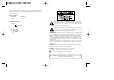
Precautions Do not install the camera in extreme temperature conditions. Do not install or use the camera in an environment where the humidity is high. Only use the camera under conditions where temperatures are between -10˚C and +50˚C. Be especially careful to provide ventilation when operating under high temperatures. It can cause the image quality to be poor. Do not drop the camera or subject them to physical shocks. It can cause malfunctions to occur.
Components and Accessories Overview 1. SID-500 2. Instruction Manual 4. M4 Tapping Screw 4EA 5. M4 Machine Screw 4EA 6. Adapter plate 7.
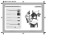
Overview Installation Pan Base control panning angle of camera Rotate Base Holding Screw fix rotated position Rotate Base control rotating angle of camera Pan Base Holding Screws (Color : Silver) fix panned position Auto Focus 10x ZOOM Lens Module. SET button To access the main setup menu. Pressing the “SET” button locks the zoom control functions of these buttons and prompts the main setup menu. RIGHT (F-FAR button) To move the arrow indicator to right.
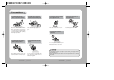
Installation Adjust the panning and tilting, rotating while watching the monitor When installing on a adapter plate An arrow for installing directions adapter plate M4 tapping screw (provided) CAMERA 1) Place the bracket provided on the installation surface and fix it with the M4 tapping screws (provided). (Select either 85X85 or 83.5X46) 2) When placing the camera body on the plate, insert the plate pin into the mounting hole on the body as shown in figure-1 and fix it by turning clockwise.
Connection Connecting to Monitor Connecting to Power Connect the VIDEO-OUT jack to the VIDEO-IN jack of monitor. CCTV Camera Connect the adaptor to the power input connector as shown in the figure below. The recommended adaptor specification for SID-500N/SID-500P is AC 24V / 500mA or DC 12V / 500mA. Monitor • As the connecting method varies with the instruments, refer to the manual supplied with the instrument. • If necessary, you can connect the monitor to the REMOTE jack on the back of your camera.
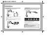
Connection Operating Your Camera RS-485 communication control Menu Configuration Connecting to RS-485 Control Cable MAIN SETUP MENU CONTROL CABLE RED (TRX+) WHITE(TRX-) SPEC RS-485+ RS-485- Using a RS-485 communication, it will be able to control the ZOOM/FOCUS and OSD menu at the SAMSUNG TECHWIN System Controller or DVR.
Operating Your Camera Menu Setup Select feature using the UP or DOWN button. Use the six buttons on back of the camera. MAIN SETUP CAM TITLE OFF WHIET BAL ATW BACKLIGHT OFF MOTION DET OFF FOCUS EXPOSURE SPECIAL RESET EXIT Change the status using the LEFT or RIGHT button. 3. Change the status of the selected feature using the LEFT or RIGHT button. 4. When completed, move the arrow indicator to 'EXIT' and press the SET button. AF button SET button RIGHT button LEFT button UP button DOWN button 1.
Operating Your Camera 3. Press SET button. 5. Select on screen position of the CAM TITLE. Move the cursor to 'POS' and press SET button. 4. You can enter up to 15 characters. Move the cursor to the character entry field using the LEFT or RIGHT button. Use UP, DOWN, LEFT, and RIGHT buttons to select a desired character. The CAM TITLE is displayed on the top-left of the monitor screen.
Operating Your Camera WHITE BALANCE CONTROL Your camera provides three 'WHITE BAL' control modes for your choosing in adjusting the white balance. 1. Press the SET button to access the main setup menu and move the indicator to 'WHITE BAL' using the UP or DOWN button. 2. Set 'WHITE BAL' using the LEFT or RIGHT button.
Operating Your Camera FOCUS MOTION DETECTION This product has a feature that allows you to observe movements of objects in 4 different areas on the screen, and the words ‘MOTION DETECTED’ appear on the screen when movement is detected; hence a single individual can conduct supervision efficiently. The camera detects an object’s movement by sensing disparity of outline, and level of brightness and color. •Please press the SETUP button. -OFF: MOTION DETECTION mode is cancelled.
Operating Your Camera •ONE PUSH : Focus is automatically adjusted just once, after zoom position is changed. Select ' ONE PUSH' and press the SET button to confirm. Increase or decrease optical zoom (ZOOM) or digital zoom (D-ZOOM) positions using the directional buttons while verifying the changes on screen. Press the SET button once desired image quality is obtained. •MANUAL : Select 'MANUAL' and press the SET button to confirm.
Operating Your Camera ZOOM POS INIT: Configure zoom position using this feature. Position the indicator ove 'ZOOM POS INIT' using the LEFT or RIGHT button. FOCUS SETUP MODE ZOOM TRK ZOOM SPEED D-ZOOM DISP ZOOM MAG ZOOM POS INIT LENS INIT AUTO ON FAST OFF OFF ON OFF Notes • Preset setting has priority over a ZOOM POS INIT setting. LENS INIT : Use this feature to initialize the lens(1x, WIDE). Position the indicator over LENS INIT. using the UP or DOWN button. Press the SET button to confirm.
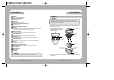
Operating Your Camera IRIS: Set 'IRIS' to 'AUTO' or 'MANUAL'. Position the indicator over 'IRIS' using the UP or DOWN button and then select the desired iris mode using the LEFT or RIGHT button. EXPOSURE SETUP BRIGHTNESS IRIS SHUTTER AGC 25....... AUTO --NORMAL •AUTO: The iris is automatically activated upon illumination. •MANUAL: Manual iris configuration. Set 'IRIS' to 'MANUAL' using the LEFT or RIGHT button and then press the SET button.
Operating Your Camera AGC (Auto Gain Control): For brighter images. 1. Position the indicator over 'AGC' using the UP or DOWN button. 2. Set 'AGC' to the desired mode using the LEFT or RIGHT button. •HIGH : Wide range gain value adjustment •NORMAL : Normal range fain value adjustment. •OFF : Disabled EXPOSURE SETUP BRIGHTNESS IRIS SHUTTER AGC SSNR SENS-UP 25....... AUTO --NORMAL LOW OFF Notes • Changing 'AGC' setting from NORMAL to HIGH results in greater sensitivity, as well as on screen noise.
Operating Your Camera •PRESET NO : Up to eight different preset configurations are supported. SPECIAL SPECIAL SETUP USER PRESET OFF PRIVACY OFF DAY/NIGHT COLOR SYNC INT COMM ADJ IMAGE ADJ END USER PRESET SETUP PRESET NO. NO. 1 PRESET MODE OFF PRESET SAVE PRESET CLEAR END PRESET DEFINED •PRESET MODE: Configure initial settings under FOCUS, EXPOSURE, etc. 1. Press the SET button to access the main setup menu and then position the indicator over 'SPECIAL' using the UP or DOWN button. 2.
Operating Your Camera •PRESET CLEAR: Clear configured preset. USER PRESET SETUP PRESET NO. NO. 1 PRESET MODE OFF PRESET SAVE PRESET CLEAR END PRESET DEFINED •END: Revert to the SPECIAL SETUP menu. •GROUP SEL : Choose up to eight groups. Each group can consist of four mask areas. •AREA SEL : Configure eight mask areas. •AREA MODE : Mask area display. •MASK TONE : Adjust desired mask color level. •TOP : To move the mask area up. •BOTTOM : To move the mask area down. •LEFT : To move the mask area left.
Operating Your Camera SYNC : Two synchronization modes are available INTERNAL and EXTERNAL LINE-LOCK. In LINE-LOCK mode, it synchronizes the camera’s video out signal to the external SYNC signal. SPECIAL SETUP USER PRESET OFF PRIVACY OFF DAY/NIGHT COLOR SYNC INT COMM ADJ IMAGE ADJ •INT : Internal synchronization •LL : External line-lock synchronization · If you choose ‘LL’, you can adjust the desired phase. Press the SET button. · You can adjust the desired phase from 0 to 359.
Troubleshooting Specifications Refer to the following table if you are experiencing trouble with your camera. Contact an authorized technician if the table does not provide you with a solution to the trouble. Problem Solution No display • Check the power cable and the wiring between the camera and the monitor. • Ensure proper video cable connection (Video Out Jack). Dim display • The lens could be dirty. Clean with a soft, clean piece of cloth. • Adjust monitor settings.
Dimension Specifications SID-500N Communication E L E C.
DECLARATION OF CONFORMITY Application of Council Directive(s) 89 / 336 / EEC Manufacturer's Name SAMSUNG TECHWIN CO., LTD Manufacturer's Address SAMSUNG TECHWIN CO., LTD 42, SUNGJU-DONG CHANGWON-CITY, KYUNGNAM, KOREA, 641-716 European Representative Name European Representative Address Equipment Type/Environment CCTV Camera Model Name SID-500P Beginning Serial NO. S6700001 Year of Manufacture 2006. 7.