
Quick Guide


5 - English
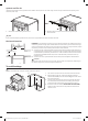
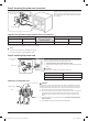
Installing a 4-wire power cord
Neutral
terminal
Live 1
Live 2
White
White
Black
Black
Red
Red
Ground wire
(Green)
Ground
screw
Ground plate
Ground strap
WARNING
The neutral wire of the supply circuit must be connected
to the neutral terminal located in the lower center of
the terminal block. The power leads must be connected
to the lower left and the lower right terminals of
the terminal block. The 4th grounding lead must be
connected to the frame of the range with the ground
plate and the ground screw.
1. Remove the 3 lower terminal screws from the
terminal block. Remove the ground screw and
ground plate and retain them.
2. Cut and discard the ground strap. Do not discard any
screws.
3. Insert the ground screw into the power cord ground
wire terminal ring, through the ground plate, and
into the frame of the range.
4. Insert the 3 terminal screws (removed earlier)
through each power cord terminal ring and into the
lower terminals of the terminal block. Be certain
that the center wire (white/neutral) is connected
to the center lower position of the terminal block.
Tighten screws securely to the terminal black.
5. Go to Step 5 on page 6 to continue with the
installation.
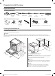
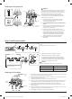
Step 4. Installing the conduit
1
1
⁄8"
1
3
⁄8"
1
3
⁄8"
1
1
⁄8"
Remove the conduit connection plate and rotate it as shown
below.
The conduit hole (1
1
⁄8") must be used.
1"
3
⁄8"
3
1
⁄2" 3
1
⁄2"
4 wire3 wire
Knockout surface
Conduit connection plate
1"
3
⁄8"
Ring
Body
Strain relief
Figure 1 Figure 2
1. Prepare the conduit cord as shown in Figure 1.
2. Install the conduit cord as shown in Figure 2.
For conduit installations, insert the strain relief (not
included) into the conduit hole (1
1
⁄8"). Then thread the
conduit cord through the body of the strain relief and
fasten the ring. Reinstall the bracket.
CAUTION
You must check voltage after connecting power cord.
Live 1 - Neutral 120 V
Live 2 - Neutral 120 V
Live 1 - Live 2 208 V / 240 V
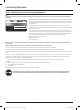
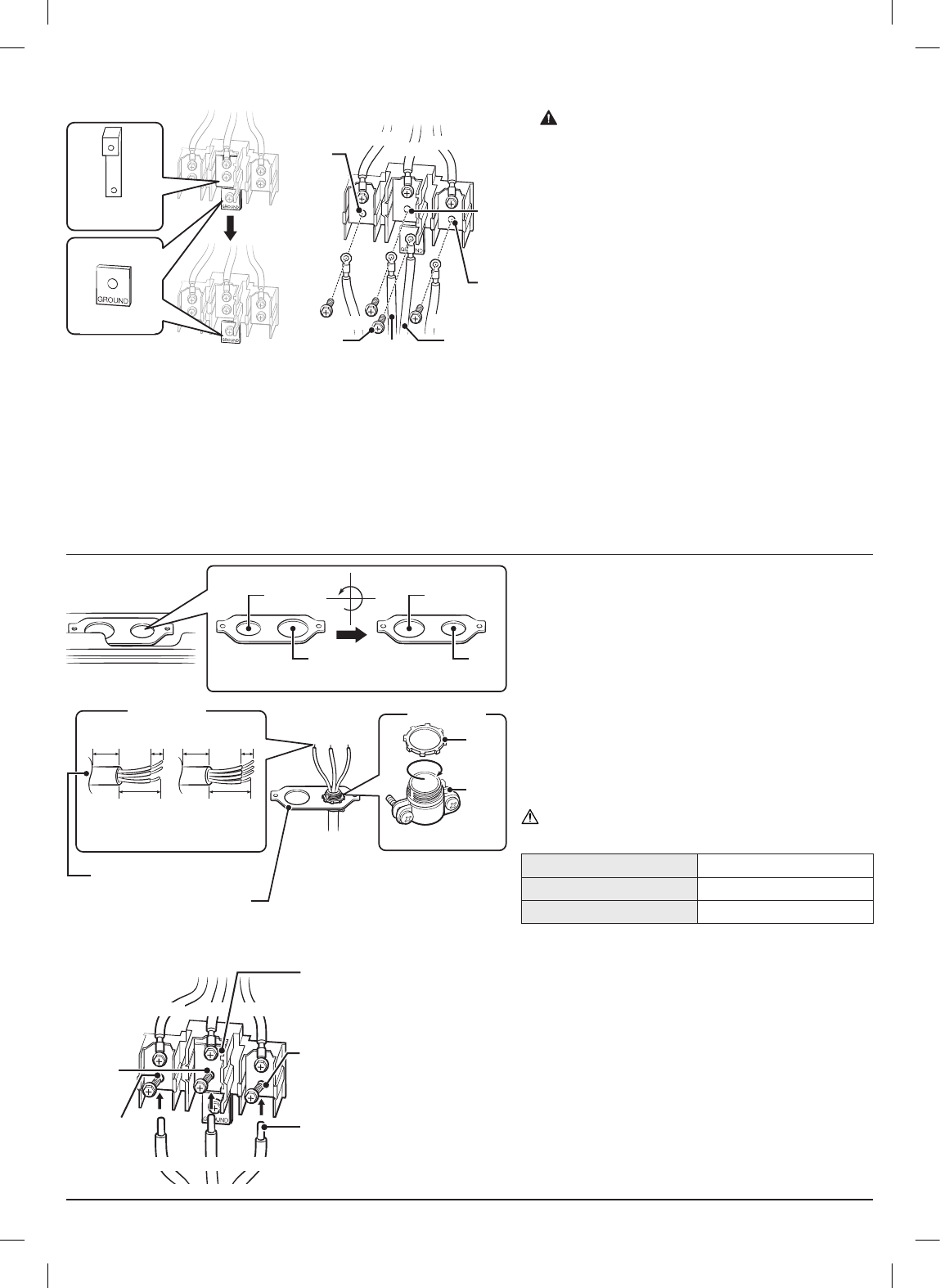
Installing a 3-wire conduit
Ground
strap
Wire tips
Neutral
terminal
Live 1
Live 2
Black White Red
Black White Red
• Aluminum building wire may be used but it must be rated for the correct amperage
and voltage. Connect the wires as described below.
• The wire you use, the location and enclosure of splices, etc., must conform to good
wiring practices and local codes.
1. Loosen the 3 lower terminal screws from the terminal block.
2. Insert the center bare wire (white/neutral) tip through the bottom center terminal
block opening. On certain models, the wire will need to be inserted through the
ground strap opening and then into the bottom center block opening.
3. Insert the two side bare wire tips into the lower left and the lower right terminal
block openings.
4. Tighten the screws until the wire is rmly secured (35 to 50 inch-lbs.). Do not over-
tighten the screws since it could damage the wires.
5. Go to Step 5 on page 6 to continue with the installation.
Install_NE63T8911_AA_DG68-01302A-01_EN+MES.indb 5Install_NE63T8911_AA_DG68-01302A-01_EN+MES.indb 5 2021-01-29 6:21:202021-01-29 6:21:20