
Datasheet


- 34 -
MMCRE64G5MXP-0VB datasheet SSD
Rev. 1.3
MMCRE28G5MXP-0VB
MMDOE56G5MXP-0VB
9.0 SATA II Optional Feature
9.1 Power Segment Pin P11
Pin P11 of the power segment of the device connector may be used by the device to provide the host with an activity indication and it may be used by the
host to indicate whether staggered spinup should be used. To accomplish both of these goals, pin P11 acts as an input from the host to the device prior to
PHYRDY for staggered spin-up control and then acts as an output from the device to the host after PHYRDY for activity indication. The activity indication
provided by pin P11 is primarily for use in backplane applications.
A host may only support one pin P11 feature, either receiving activity indication or staggered spin-up disable control. If a host supports receiving activity
indication via pin P11, then the host shall not use pin P11 to disable staggered spin-up. If a host does not support receiving activity indication via pin P11,
then the host may use pin P11 to disable staggered spin-up.
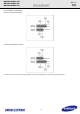
9.2 Activity LED indication
The signal provides for activity indication is a low-voltage low-current driver intended for efficient integration into present and future IC manufacturing pro-
cesses. The signal is NOT suitable for directly driving an LED and must first be buffered using a circuit external to the drive before driving an LED.
9.3 Asynchronous Signal Recovery
Phys may support asynchronous signal recovery for those applications where the usage model of device insertion into a receptacle does not apply. When
signal is lost, both the host and the device may attempt to recover the signal. A host or device shall determine loss of signal as represented by a transition
from PHYRDY to PHYRDYn, which is associated with entry into states LSI: NoCommErr or LS2:NoComm within the Link layer. Note that negation of
PHYRDY does not always constitute a loss of signal. Recovery of the signal is associated with exit from state LS2:NoComm. If the device attempts to
recover the signal before the host by issuing a COMINIT, the device shall return its signature following completion of the OOB sequence which included
COMINIT. If a host supports asynchronous signal recovery, when the host receives an unsolicited COMINIT, the host shall issue a COMRESET to the
device. When a COMRESET is sent to the device in response to an unsolicited COMINIT, the host shall set the Status register to 7Fh and shall set all
other Shadow Command Block Registers to FFh. When the COMINIT is received in response to the COMRESET which is associated with entry into state
HP2B:HR_AwaitNoCOMINIT, the Shadow Status register value shall be updated to either FFh or 80h to reflect that a device is attached.