
Datasheet


- 15 -
MMCRE64G5MXP-0VB datasheet SSD
Rev. 1.3
MMCRE28G5MXP-0VB
MMDOE56G5MXP-0VB
6.0 Shadow Register Block registers Description
6.1 Command Register
This register contains the command code being sent to the device. Command execution begins immediately after this register is written. All other registers
required for the command must be set up before writing the Command Register.
6.2 Device Control Register
This register contains the command code being sent to the device. Command execution begins immediately after this register is written. All other registers
required for the command must be set up before writing the Command Register.
6.2.1 1 Field / bit description
• HOB is defined by the 48bit Address feature set. A write to any Command register shall clear the HOB bit to zero.
• SRST is the host software reset bit. SRST=1 indicates that the drive is held reset and sets BSY bit in Status register. Setting SRST=0 re-enables the
device.
• nIEN is the enable bit for the device Assertion of INTRQ to the host. When nIEN=0, and the device is selected by Drice select bit in DEVICE/HEAD reg-
ister, device interrupt to the host is enabled. When this bit is set, the "I’ bit in the Register Host to Device, PIO setup, Set Device Bits and DMA Set Up will
be set, whether pending interrup is found or not.
6.3 Device / Head Register
6.3.1 1 Field / bit description
The content of this register shall take effect when written.
• L : Binary encoded address mode select. When L=0, addressing is by CHS mode. When L=1, addressing is by LBA mode.
• DEV: Device select. Cleared to zero selects Device 0. Set to one selects Device1.
• HS3, HS2, HS1, HS0 : Head select bits. The HS3 through HS0 contain bits 24-27 of the LBA. At command completion, these bits are updated to reflect
the current LBA bits 24-27.
6.4 Error Register
This register contains the command code being sent to the device. Command execution begins immediately after this register is written. All other registers
required for the command must be set up before writing the Command Register.
6.4.1 1 Field / bit description
7 6 5 4 3 2 1 0
ICRC UNC 0 IDNF 0 ABRT TKONF AMNF
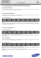
• IC
RC: Interface CRC Error. CRC=1 indicates a CRC error has occurred on the data bus during a Ultra-DMA transfer.
• UNC: Uncorrectable Data Error. UNC=1 indicates an uncorrectable data error has been encountered.
• IDNF: ID Not Found. IDN=1 indicates the requested sector’s ID field cound not be found .
• ABRT: Aborted Command. ABT=1 indicates the requested command has been aborted due to a device status error or an invalid parameter in an output
register.
• TKONF: Track 0 Not Found. T0N=1 indicates track 0 was not found during a Recalibrate command.
• AMNF: Address Mark Not Found. When AMN=1, it indicates that the data address mark has not been found after finding the correct ID field for the
requested sector.
76 5 43 2 10
HOB - - - - SRST nIEN 0
76543210
- L - DEV HS3 HS2 HS1 HS0