
Datasheet


- 10 -
MMCRE64G5MXP-0VB datasheet SSD
Rev. 1.3
MMCRE28G5MXP-0VB
MMDOE56G5MXP-0VB
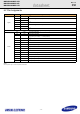
4.2 Pin Assignments
NOTE :
Uses 5V power only. 3.3V and 12V power are not used.
No. Plug Connector pin definition
Signal
S1 GND
2
nd
mate
S2 A+ Differential signal A from Phy
S3 A-
S4 GND
2
nd
mate
S5 B- Differential signal B from Phy
S6 B+
S7 GND
2
nd
mate
Key and spacing spearate signal and power segments
Power
P1 V33 3.3V power (Unused)
P2 V33 3.3V power (Unused)
P3 V33
3.3V power, pre-charge, 2
nd
mate (Unused)
P4 GND
1
st
mate
P5 GND
2
nd
mate
P6 GND
2
nd
mate
P7 V5
5V power, pre-charge, 2
nd
mate
P8 V5 5V power
P9 V5 5V power
P10 GND
2
nd
mate
P11 DAS/DSS Device Activity Signal
P12 GND
1
st
mate
P13 V12
12V power, pre-charge, 2
nd
mate (Unused)
P14 V12 12V power (Unused)
P15 V12 12V power (Unused)