
Product specifications


Troubleshooting
5-8
Samsung Electronics
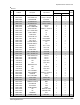
5-3-3 Detailed Procedure
No.
1
2
3
4
5
Malfunction
Pull out the power plug from the
AC terminal and confirm the fuse
on the PCB assembly
Turn the power on.
If lamp blinks trouble is not
related to the items 1 through 4
on the right.
Set operating mode when RMC
switch pushed.
Except for [FAN]mode and
[TIMER] mode.
Set operating mode when RMC
switch pushed.
1. COOL mode
2. Fan speed [AUTO]
3. Set temperature lower
than room temperature
4. Continuously operation.
Set operating mode when
RMC switch pushed.
1. [FAN] mode
2. Fan speed [Hi]
3. Continuously operation
Checking point (symptoms)
1. Is the fuse blown?
Voltage check
1. AC voltage at both end of transformer Primary?
198 - 264V~
2. AC voltage at both end of transformer secondary?
14- 18Vac
3. DC voltage at OUT and GND of IC01
(KA7812)? 12VDC
4. DC voltage at OUT and GND of IC02? 5VDC
5. DC voltage at Q201 Base and GND change?
squarewave
Voltage check
1. Voltage of relay (RY71) coil Voltage at
pin#12, pin#5 of IC07 : 12VDC
2. Voltage at Terminal Tap (TB71 or 72) and
RY71 Terminal N0 3 . 198- 264V~
1. Compressor does not operate.
1. Voltage at 3 5 both ends of CN73 :
above 180V~
2. Indoor unit fan motor does not operate.
Causes
1. Voltage over
2. Indoor unit fan motor short-circuit.
1. Irregular power code or power fuse,
or poor wiring.
2. Transformer is faulty.
3. Power circuit is faulty.
4. Power circuit is faulty.
5. Q201 is faulty.
D101~D104 (1N4007x4)
1. Relay(RY 71) coil is open.
IC07 is faulty.
2. Relay(RY 71) contactor is faulty.
1. Temperature of Heat exchange
is lower.
2. PCB is faulty.
3. Room sensor or Heat exchanger
temperature sensor is faulty
1. Indoor unit fan motor is faulty.
2. Poor connection of indoor fan motor
and connector of RPM sensing (CN43)