
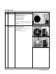
Product specifications


Samsung Electronics
5-4
Troubleshooting
5-2-3 When the Outdoor Unit Does Not Operate. (Initial Diagnosis)
1 ) Checklist :
(1) Is input voltage normal?
(2) Is the set temperature of the remote control higher than room temperature in COOL m o d e ?
(3) Is the POWER IN connector (terminal-tab) linked corre c t l y ?
(4) Is the outdoor unit properly connected with the TERMINAL BLOCK connector(5P)?
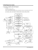
2 ) Troubleshooting pro c e d u r e
(1) Checking pro c e d u res for the indoor unit.
After unplugging out the power cord should be
reconnected within five seconds.
Does the operating lamp blink
YES
YES
NO
NO
NO 1
YES 3
2
NO
YES
1 NO
2 NO
A Room operation
“A”Compreessor or outdoor fan-motor replaced
Power relay is
out of order
Power relay should be
replaced.
PCB should be
checked.
Microcomputer is
out of order.
PCB should be checked.
Room temperature sensor is
out of order
Check as in the procedure "No Power parts"
Refer to page 5-2.
YES 3
Is the room sensor normal register?
10°C 20°C 30°C
17.96k Ω 12.09k Ω 8.3k Ω
Does the timer lamp blink during operation ?
Is the power relay RY71 operated by adjusting the
room temperature?
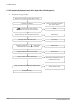
1) Is AC 198 - 264V applied relay between Terminal Tap(TB71)
and RY 71 terminal No. 3
2) Is AC 198 - 264V applied relay between Terminal Tap(TB71)
andCN 71 terminal No. 1
B Room or C Room operating
Proceed to the checking points for the outdoor unit.
Test rod location Normal
+ - Condition Voltage
IC1 Pin No.63 GND RY73 ON DC 4.8V
IC1 Pin No.62 GND RY72 ON DC 4.8V