
Product specifications


Indoor unit
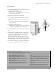
Outdoor unit Terminal Block
4
FAN
2
(N)
4
FAN
1
(L)
1(L) 2(N)
3
COMP
3
COMP
A-unit
Earth
terminal
Earth
terminal
Circuit Breaker
(Main Power cable)
Earth
terminal
B-unit
3-8
Samsung Electronics
3-2-2(e) Outdoor unit installation
Operating Instructions and Installation
GAS LEAK TEST
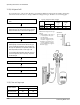
WIRING CONNECTION
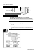
Indoor unit check point
Outdoor unit check point
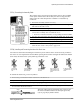
Check for gas leak from the flare nut connections with leak detector.
Two electric cables must be connected to the outdoor unit:
• The assembly cable connecting the indoor unit to the outdoor unit.
• The power cable connecting the auxiliary circuit breaker to the outdoor unit.
1 Remove the terminal board cover on the side of the outdoor unit.
2 Connect the assembly cable to terminals 1 to 5 and connect the power cable to therminals A to B.
Each wire is labelled with the corresponding terminal number.
E n s u re that the wire number of the indoor unit and the terminal number of the out-
door unit.
3 Connect the earthing wires to the earth terminals.
Refer to the page opposite for further details on how to check that earthing is cor-
re c t .
4 Replace the terminal board cover, carefully tightening the screw.
5 connect the power cable to the auxiliary circuit breaker.