LED TV Installation manual imagine the possibilities Thank you for purchasing this Samsung product. To receive more complete service, please register your product at www.samsung.com/register Model [HG890_ZA]Install_Guide-00ENG.indd 1 Serial No.
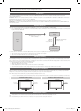
Figures and illustrations in this User Manual are provided for reference only and may differ from actual product appearance. Product design and specifications may be changed without notice. Introduction This TV has functionality that lets it interact with a set-back box (SBB/STB) and with other TVs in a computer-controlled system for hotels and other hospitality businesses. Interactive : When the TV is powered-up initially, it sends a command to identify the connected SBB/STB.
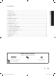
Contents Introduction............................................................................................................................................................... 2 Operational Modes.................................................................................................................................................... 2 Still image warning..............................................................................................................................................
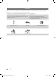
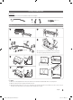
Accessories ✎✎Please make sure the following items are included with your LED TV. If any items are missing, contact your dealer. ✎✎The items’ color and shape may vary, depending on the model. ✎✎The parts for the stand are listed under Stand Components on the following page.
Installing the LED TV Stand Components When installing the stand, use the provided components and parts. L A R B C 1 EA x8 (M4 X L12) 2 EA yy Stand (depending on the model) yy Guide Stand 1 2 3 4 C x4 (M4 X L12) yy Screws ✎✎Lay the TV on a soft surface, screen side down. ✎✎Use the packing material to protect the screen. 5 6 C x4 (M4 X L12) ✎✎NOTE yy Make sure to distinguish between the front and back of the Stand and Stand Guide when connecting them.
Using the TV's Controller ✎✎The color and shape of the TV Controller may vary depending on the model. ✎✎The TV's Controller, a small joy stick like button on the bottom right side of the TV, lets you control the TV without the remote control. Open Smart Hub. Open the menu. m Select a source. R P Turn off the TV. TV Controller The control stick is located at the lower-left corner on the back of the TV.
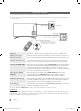
The Connection Panel 1 VARIABLE AUDIO OUT 2 VOL-CTRL 3 (HDD 5V 1A) 4 5 AUDIO OUT 6 DVI AUDIO IN 7 HDMI IN 3 EX-LINK RJP HDMI IN 1 (ARC) DATA 8 7 9 AIR/CABLE 0 ! @ ✎✎Whenever you connect an external device to your TV, make sure that power on the TV and the device is turned off. ✎✎When connecting an external device, match the color of the connection terminal to the cable. 1 VARIABLE AUDIO OUT: Used for the audio output to the Bathroom speaker.
7 HDMI IN 1 (ARC), 2 (DVI), 3: Connects to the HDMI jack of a device with an HDMI output. ✎✎ No sound connection is needed for an HDMI to HDMI connection. HDMI connections carry both audio and video. ✎✎ Use the HDMI IN 2(DVI) jack for a DVI connection to an external device. Use a DVI to HDMI cable or DVI-HDMI adapter (DVI to HDMI) for the video connection and the PC/DVI AUDIO IN jacks for audio. 8 EX-LINK: The EX-LINK connection is for service only.
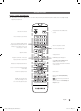
The Remote Control Remote Control (AA59-00817A) ✎✎This remote control has Braille points on the Power, Channel, and Volume buttons and can be used by visually impaired customers. Display and select the available video sources. Turns the TV on and off. Press to directly access channels. Press to select additional digital channels being broadcast by the same station. For example, to select channel ‘54-3’, press ‘54’, then press '-' and ‘3’. Adjust the volume. Return to the previous channel.
Installing batteries (Battery size: AAA) Match the polarity of the batteries to the symbols in the battery compartment. X Y Z After you have installed the batteries, use a screwdriver to screw in the screw that holds the battery cover closed. ✎✎ NOTE •• Use the remote control within 23~33 feet of the TV. •• Bright light may affect the performance of the remote control. Avoid using near fluorescent lights or neon signs. •• The color and shape of the remote may vary depending on the model.
Using the Smart Touch Control Smart Touch Control (AA59-00830A) ✎✎This remote control has Braille points on the Power, Channel, and Volume buttons and can be used by visually impaired customers. Use Voice Recognition function with the microphone embedded in remote control. ✎✎The Voice Recognition function can be affected by unclear pronunciation, voice level, or surrounding noise. Not Available TV STB MIC Turns the TV on and off.
Connecting to the TV In order to operate the TV using a Smart Touch Control, you must first pair it to the TV via Bluetooth. However, the Smart Touch Control is only available for the paired Samsung TV. 1. To turn on the TV, point the Smart Touch Control at the remote control receiver of the TV and press the P button. The remote control receiver's location may vary depending on the model. 2. A Bluetooth icon will appear at the bottom left of the screen as shown below.
Reconnecting the Smart Touch Control If you need to reestablish the connection between the TV and the Smart Touch Control, press the pairing button at the back of the Smart Touch Control, pointing at the remote control sensor of the TV. The pairing button can be accessed by removing the Smart Touch Control's battery cover. Pressing the pairing button automatically reestablishes the connection between the Smart Touch Control and the TV.
Using the touch pad Use the touch pad to implement various commands. Navigate to Tutorial (System > Device Manager > Smart Touch Control Settings > Tutorial) to view an on-screen guide to using the Smart Touch Control. Dragging HOME Tap HOME Drag on the touch pad to move the focus, pointer, or highlight in the direction the finger is dragging. HOME HOME Press the touch pad to select the item highlighted or in focus.
Using the Virtual Remote Panel Press the MORE button to display the virtual remote panel on the TV screen. The virtual remote panel consists of the number panel, a playback control panel, and the quick access panel. Use the touch pad to highlight and select icons, numbers, and buttons on the panels. ✎✎The displayed virtual remote panel on the TV screen may differ depending on the country. Channel History D E F G No Channel numbers have been saved.
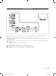
Connecting to the Network You can set up your TV so that it can access the SMART TV applications through your local area network (LAN) using a wired or wireless connection. ✎✎After you have “physically” connected your TV to your network, you must configure the network connection to complete the process. You can configure the connection during the Initial Setup process (see page 35) or after the Initial Setup process, through the TV’s menu.
Network Connection - Wired There are three main ways to connect your TV to your network using cable, depending on your network setup.
Connecting the TV to an SBB or STB ETH MODEM Data Cable TV Rear Panel DATA 1. Connect the DATA jack of the TV to the [ETH MODEM] jack of the STB (SBB) with the Data cable. ✎✎ Use data communication. ¦¦ Connecting the Audio Output to an Audio Amplifier TV Rear Panel AUDIO IN AUDIO OUT 1 Stereo cable DVI AUDIO IN Audio Amplifier HDMI IN 3 1. Connect the AUDIO OUT port of the TV to the Audio In port of an audio amplifier with a stereo cable. 18 English [HG890_ZA]Install_Guide-00ENG.
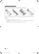
¦¦ List of Vendors and Compatible Data Cables Supplied with the TV yy Confirm that you are using the correct data cable for your vendor. Refer to the code label on the data cables. English [HG890_ZA]Install_Guide-00ENG.
Connecting the Bathroom Speakers You can connect the Bathroom Speakers using the following method. ¦¦ Connecting through the Variable Output (available without an external amplifier) TV Rear Panel VARIABLE AUDIO OUT 1 Speaker VOL-CTRL (HDD 5V 1A) 2 VOL+ VOL- Volume Control Box 1. Connect the VARIABLE AUDIO OUT port of the TV to the Bathroom Wall Speakers of the hotel. Speaker + Speaker - N/C 2.
Connecting the MediaHub HD Output to any external source connected to MediaHub HD on the hotel desk. MediaHub HD Rear TV Rear Panel HDMI USB RS/232 VARIABLE OUT A AUDIO VOL-CTRL 2 HDMI cable ((HDD 5V 1A) AUDIO OUT DVI AUDIO IN HDMI IN 3 EX-LINK RJP HDMI IN 1 (ARC) DATA AIR/CABLE 1 RS-232 Data Cable 1. Connect the EX-LINK port of the TV and the RS/232 port of the MediaHub HD. 2. Connect the HDMI IN (1(ARC), 2(DVI) or 3) port of the TV and the HDMI port of the MediaHub HD.
Connecting the RJP (Remote Jack Pack) Connect the input jacks on the TV to the RJP. The RJP lets guests connect audio and video sources to the TV. RJP Rear USB HDMI S-VIDEO RCA RS/232 TV Rear Panel VARIABLE AUDIO OUT 2 HDMI cable VOL-CTRL 1 Video / Audio Cable (HDD 5V 1A) AUDIO OUT DVI AUDIO IN HDMI IN 3 EX-LINK RJP HDMI IN 1 (ARC) DATA AIR/CABLE 3 RS-232 Data Cable 1. Connect the AV IN [L-AUDIO-R] port of the TV to the RCA port of the RJP. 2.
yy RJP (Remote Jack Pack): RJP stands for Remote Jack Pack. The RJP is a hardware module that has different Audio Video inputs (A/V, Audio, PC and HDMI) and corresponding outputs. The corresponding outputs are connected from the RJP to the TV. The RJP communicates with the TV via RS232. A Hot Plug & Play function allows hotel guests to connect an external source to the RJP. The RJP communicates with the TV by sending messages regarding Active/Inactive sources.
Setting the Hotel Option Data To let you control how the TV functions when in Hotel mode, the TV has two Hotel mode menus, the Stand-alone mode menu and the Interactive mode menu. The menu items that differ between the menus are listed below.
¦¦ Menu Items To Enter this menu: Press the MUTE → 1 → 1 → 9 → ENTER buttons in order. To exit from this menu : Power Off (or Power Off and unplug if you have changed SI Vendor), and then turn on again. Any changes you made are saved.
Menu Music Mode Item initial Value Description Music Mode AV OFF Allows music output from an mp3/audio player connected to an AV Input Source on the TV. When on, you can hear sound from the player through the TV whether there is a video signal or not. Also mutes the video so the TV does not display a picture when a guest is playing music. The TV's backlight, however, remains on. Music Mode Comp OFF To get music output from an mp3/audio player through a Component Input Source.
Menu Item initial Value Welcome Message OFF Edit Welcome Message Hospitality Logo Edit the Welcome Message. OFF Logo/ Message Turns the Hospitality logo feature on/off. Select from Off, BMP, AVI, or Both. When you select BMP, AVI, or Both, you select the file to use and turn the logo feature on. The Logo is shown during the initial turn on for the amount of time set in "Logo Display Time" Hospitality Logo DL ... Downloads the Hospitality logo.
Menu Item initial Value Widget Mode OFF Solution Type Vender Server Server URL Setting Select type of solution (Vender Server/ SINC Server). Set server URL. License Server IP Setting Set server IP. Widget Service Description Widget Mode ON/OFF. Virtual Standby mode On/Off. When Virtual Standby is On, TV power consumption will be 9.5W to 17.4W (Depending on the size of the TV screen). Virtual Standby OFF IPTV Mode ... IPTV mode On/Off. External Source Browser ON Source Menu On/Off.
¦¦ Welcome Message The Welcome Message feature displays a custom message on the TV every time it is turned on. –– Welcome message settings are in the Hotel Option Menu. –– Set Welcome Message to ON to display the message when the TV is powered on. Welcome Message OFF Edit Welcome Message Hospitality Logo OFF Hospitality Logo DL ... Logo Display Time ... –– You can make the Welcome Message up to 25 characters long and edit it in the Hotel Service menu.
¦¦ Hospitality Logo The Hospitality Logo function displays the Hotel's picture image when the TV is powered on. –– Hospitality Logo settings are the Hotel mode menus. –– The Logo Download and Logo Display Menu items are enabled when you turn the Hospitality Logo option on. –– If there is a logo image stored in memory and the Hospitality Logo option is on, the Hospitality logo is displayed when the TV is turned on.
¦¦ USB Cloning The USB Cloning function lets you download user-configured settings (Picture, Sound, Input, Channel, Setup, and Hotel Setup) from one TV to a USB device, and then upload these settings from the USB device to other TV sets. This lets you create a standard array of settings and distribute that standard array to all the TVs in your facility. yy Cloning from TV to USB: Copies stored menu settings from a TV to a USB device. 1. Insert a USB drive into the USB port on the rear of the TV. 2.
yy Settings Cloned in the Hotel Menu Menu Item Hospitality Mode SI Vendor Power On Channel EN Power On Channel Channel Type Power On Volume EN Power On Volume Min Volume Max Volume Power On Source Power On Option Channel Setup Channel Editor Channel Bank Editor Channel Bank Service Level Mixed Channel Map Dynamic SI Channel Rescan Message Pan Euro MHEG Channel Auto Store Mychannel En Genre Editor Picture Menu Lock Menu Display Channel Menu Display Panel Button Lock Mute On CC Subtitle Auto On SW Clock Local
Menu Item Hospitality Logo Hospitality Logo DL Logo Display Time Clone TV to USB Clone USB to TV Setting Auto Initialize REACH Server update Time REACH Update Immediate Manual SIRCH REACH Server Channel REACH Server Version REACH Server Group ID REACH Server IPG Room Type CAS PI AES Data Self Diagnosis PI AES Log View PI AES Log Upgrade now Service Pattern ATV Cable AGC Gain DTV OpenCable AGC Gain TV Reset Cloning Support Applicable Region Yes N/A Yes N/A N/A Yes Yes Yes N/A Yes N/A No Yes No Yes N/A N/A
¦¦ Multi Code Remocon A Multi Code Remocon is a special remote which is designed to control multiple TV. This is useful where there is more than one TV in a location. You can control up to 10 TVs, each with a different ID code, with one remote. ID numbers are displayed on each TV's OSD. The Initial ID code for each TV is “0”. –– You can set and reset the ID code in Analog TV mode or PC mode. (Not available in DTV mode.) –– You can set the ID code to any digit from 0 to 9.
¦¦ Setting Auto Initialize When you clone settings from one TV to another, you clone both the guest side menu and hotel side menu settings: Picture, Sound, Input, Channel, Setup, and Hotel Setup. This lets you set nearly all of the menu values on your hospitality TVs to the same, standard settings. If you allow guests access to the guest side menus, for example the Picture menu, they can change the settings in those menus so they are no longer standard.
¦ Hotel Plug & Play The Hotel Plug & Play function, which automatically performs the Hotel mode selection, Country Setup, Clock Setup, and Picture Mode Setup, runs once, when power is first turned ON. Setup also runs automatically after you have executed a Service Reset. y UI Scenario Local Set Local Set If you select Change Change Local Set if Located in North America Latin America and Europe. In other regions, Please press SKIP button move to the next step.
yy Hotel Plug & Play OSD –– Initially highlighted: Interactive –– If you select the Standalone Only button, the Standalone hotel mode is set by default and the “Standalone mode is set” OSD appears for 3 seconds. –– TV enters into RF mode automatically after displaying the “Standalone mode is set” OSD for 3 seconds. –– If you select the Interactive mode, the Interactive Setup Menu is displayed. Press the power off key to exit from the Interactive menu.
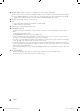
3. Press the ▲ or ▼ button to select SW Upgrade, and then press the ENTER button. The message "Scanning for USB. This may take more than 1min." is displayed. 4. The message "Upgrade version XXXX to version XXXX? The system will be reset after upgrade." is displayed. Press the ◄ or ► to select the OK, and then press the ENTER button. AUDIO OUT VOL-CTRL (HDD 5V 1A) Please be careful to not disconnect the power or remove the USB drive while upgrades are being applied.
¦¦ Channel Bank Editor (Smoovie TV Only) The Channel Bank Editor in conjunction with the SMOOVIE remote lets you control the channels guests have access to. The Channel Bank Editor provides three Banks of channels and lets you select which channels will be available from each bank. SMOOVIE remotes have installable Bank Cards which correspond to the channel banks in the Channel Bank Editor. The remotes only allow access to channels in the channel bank that correspond to the installed card.
Smoovie Set Up Sequence Smoovie TV Setup (Air/ Cable ) Only Air or Cable used Only Air or Cable used If the TV starts with Hotel Plug&Play If Hotel Plug&Play already done 1 Do a complete P&P (including Air or Cable auto tune) Enter the Hotel menu 2 After P&P, the TV displays the Hotel menu Select the channel type - ATV or ADTV for Air - CATV or CDTV for cable 3 Select the channel type - ATV or ADTV for Air - CATV or CDTV for cable Select Smoovie TV in the Hotel menu 4 Select Smoovie TV in the
The picture below shows a sample Channel Editor screen. yy a Indicates an analog channel. yy Channels without an a are digital channels. yy The guide at the bottom of the Channel Editor menu displays the remote buttons you need to press to apply Channel Editor functions. 1 Using the remote's up or down arrow key, highlight the channel that you want edit. –– To edit more than one channel, move the highlight to a channel, and then press the ENTERE key.
When you press the TOOLS button, the following menu is available. Edit Channel Number Use Edit Channel Number to change the channel number of a channel you select. To change a channel number, follow these steps: 1. Select a channel on the Channel Edit screen. Channel 2. Press the Tools button on your remote. TOOLS aChannel 10 Rename 3. Select Edit Channel Number in the Tools menu. Air 10-1 CW CW DTV Edit Channel Number a 11 HBO Information Air 11-1 HBO DTV 4.
The external sources of this TV are displayed in the last page of the Channel Editor menu as shown in the example below. In the example, there are two external sources connected to the TV, HDMI2(DVI) and AV. –– You can assign a new analog channel to an external source by selecting the source on the last page, pressing the Tools button, selecting Edit Channel Number, and then using the up or down arrow button on the remote to select the channel number of the analog channel.
Installing a Wall Mount Using the Wall Mount Adapter To install a wall-mount from another manufacturer, user the Holder-Ring. ✎✎ For more detailed information, refer to the User Manual of the Wall Mount Kit. Wall Mount Kit Specifications (VESA) ✎✎The wall mount kit is not supplied, but sold separately. Install your wall mount on a solid wall perpendicular to the floor. If you are attaching the wall mount to building materials other than plaster board, contact your nearest dealer.
Assembling the Cable clip Assembling the Screw Cover Assembling the Power inlet Cover English [HG890_ZA]Install_Guide-00ENG.
Securing the TV to the Wall Caution: Pulling, pushing, or climbing on the TV may cause the TV to fall. In particular, ensure your children do not hang on or destabilize the TV. Doing so may cause the TV to tip over, causing serious injuries or death. Follow all safety precautions provided in the Safety Flyer included with your TV. For added stability and safety, you can purchase and install the anti-fall device as described below.
4. Fasten the Holder to the cabinet using a wood screw. ✎✎ Using an M5 x L35 or a larger screw. 5. Fasten the Holder with a screw the same way used when attaching it to a cabinet. Make sure to stretch the Holder cord tight. If the rack is made of steel or glass, attach the holder onto the wall. ✎✎ When attaching the holder onto a wall, use an anchor compatible with the wall's material. When attaching the holder onto a wall, use an anchor compatible with the wall material.
Anti-theft Kensington Lock The Kensington Lock is a device you can use to physically fix a TV to a location when you use it in a public place. The appearance and locking method may differ from the illustration at right, depending on the manufacturer. Refer to the manual provided with the Kensington Lock for additional information on proper use. 1 The Kensington Lock is not supplied by Samsung. ✎✎Please find the “K” icon on the rear of the TV. A Kensington slot is beside the “K” icon.
Specifications Display Resolution Environmental Considerations Operating Temperature Operating Humidity Storage Temperature Storage Humidity Stand Swivel (Left / Right) Model Name Screen Size (Diagonal) Sound (Output) Dimensions (WxDxH) Body With stand Weight Without Stand With Stand Model Name Screen Size (Diagonal) Sound (Output) Dimensions (WxDxH) Body With stand Weight Without Stand With Stand 1920 x 1080 50°F to 104°F (10°C to 40°C) 10% to 80%, non-condensing -4°F to 113°F (-20°C to 45°C) 5% to 95%, n
Dimensions HG46NB890 / HG55NB890 / HG65NB890 ▪▪ Front view / Side view 4 1 2 3 5 (unit: Inches) 1 40.6 HG46NB890 2 23.6 3 24.9 4 1.3 5 10.1 HG55NB890 48.1 27.8 29.2 1.3 12.2 HG65NB890 56.98 32.98 34.49 1.51 13.00 ▪▪ Jack panel detail / Rear view VARIABLE AUDIO OUT 3 2 VOL-CTRL 1 (HDD 5V 1A) 4 AUDIO OUT DVI AUDIO IN 5 HDMI IN 3 EX-LINK RJP HDMI IN 1 (ARC) AIR/CABLE DATA (unit: Inches) HG46NB890 50 1 2 3 4 5 7.8 7.8 16.3 5.6 10.7 HG55NB890 15.7 15.7 16.2 5.
¦¦ Important Warranty Information Regarding Television Format Viewing ✎✎ See the warranty card for more information on warranty terms. Wide screen format LED Displays (16:9, the aspect ratio of the screen width to height) are primarily designed to view wide screen format full-motion video. The images displayed on them should primarily be in the wide screen 16:9 ratio format, or expanded to fill the screen if your model offers this feature and the images are constantly moving.
Contact SAMSUNG WORLDWIDE If you have any questions or comments relating to Samsung products, please contact the SAMSUNG customer care center. Samsung Hospitality Hotline: 866-894-0524 Web site: http://www.samsung.com/us/business HG890-ZA-00 [HG890_ZA]Install_Guide-00ENG.