a. hu lim ek ev .k w w w "EEE Yönetmeliğine Uygundur" "This EEE is compliant with RoHS" NS***4PXEA_IM_E_32787A(8).
Cassette Type Series a. hu ACFB4DEH ACFB4PEH ACFB4FEH NS4PXEA NS4DXEA NS4ZXEA lim Air Conditioner w w w .k ev ek installation manual imagine the possibilities Thank you for purchasing this Samsung product. To receive more complete service, please register your product at www.samsung.com/register E S F I P D G R DB98-32787A(8) NS***4PXEA_IM_E_32787A(8).
Contents a. hu Preparation for installation . .............................................................................................................................................................................................. 3 Deciding on where to install the indoor unit . .......................................................................................................................................................... 4 Indoor unit installation . ........................................
Our units should be installed in compliance with the spaces shown in the installation manual, to ensure accessibility from both sides and allow repairs or maintenance operations to be carried out. The unit’s components should be accessible and easy to disassemble without endangering people and objects.
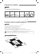
Preparation for installation Accessories The following accessories are supplied with the indoor unit. The type and quantity may differ depending on the specifications. Insulation pipe Cable-tie Drain hose Installation manual Clamp lim a. hu Insulation cover band Deciding on where to install the indoor unit ek Indoor unit ev There must be no obstacles near the air inlet and outlet. Install the indoor unit on a ceiling that can support its weight.
When installing a cassette type indoor unit on the ceiling and its installation condition is temperature over 27°C and humidity over 80%, install a 10mm thickness of polyethylene insulation or similar type of insulation on the indoor unit body. D E B A ENGLISH Insulation installation guide Cut the part where pipes are pulled out or some curved part for insulating work. When insulating a connecting duct, the outlet and inlet part (front, back) should be insulated together.
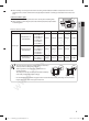
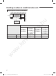
Deciding on where to install the indoor unit Required space for an indoor unit installation 1500mm or more 2500mm or more 17mm 20mm a. hu ‘C’mm Obstruction MODEL Net dimension mm 251 293 335 335 840×246×840 840×288×840 840×288×840 ek mm 840×204×840 w w w .
Drawing of the indoor unit ENGLISH 890~910 (Celling opening) 950 Unit : mm 55 a. hu ek lim 735 (Suspension position) 950 890~910 (Celling opening) 735 (Suspension position) 840 370 346 185 840 55 45 330 w 204 253 840 X 204 X 840 15.0 1/4" 1/2" 216 300 MODEL w w A mm B mm Net dimension mm Net weight kg Liquid pipe connection Gas pipe connection Drain Hose connection mm 240 270 Sub duct connection 071FB4D 052FB4D 0714DX 164 86 96 120 ev A .
Indoor unit installation When deciding on the location of the air conditioner with the owner, the following restrictions must be taken into account. 1. Determine the position of the pipe and drain hose hole as seen in the picture and drill the hole with an inner diameter of 65mm so that it slants slightly downwards. 2. Insert bolt anchors, use existing ceiling supports or construct a suitable support as shown in figure. 3. Install the suspension bolts depending on the ceiling type. a.
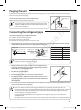
Purging the unit From factory the unit is supplied and set with a pre-charge of nitrogen gas. (insert gas) Therefore, all insert gas must be purged before connecting the assembly piping. Unscrew the pinch pipe at the end of each refrigerant pipe. • To prevent dirt or foreign objects from getting into the pipes during installation, do NOT remove the pinch pipe completely until you are ready to connect the piping. Gas refrigerant port a.
Cutting/Flaring the pipes 1. Make sure that you have the required tools available. (pipe cutter, reamer, flaring tool and pipe holder) 2. If you wish to shorten the pipes, cut it with a pipe cutter, taking care to ensure that the cut edge remains at a 90° angle with the side of the pipe. Refer to the illustrations below for examples of edges cut correctly and incorrectly. Oblique Pipe cutter Rough Burr a. hu Pipe 3.
Performing leak test & insulation Leak test ENGLISH To identify potential gas leaks on the indoor unit, inspect the connection area of each refrigerant pipe using a leak detector for R410A. Before recreating the vacuum and recirculating the refrigerant gas, it is advisable to pressurize the whole system with nitrogen (using a cylinder with pressure reducer) at a pressure above 40 bar in order to immediately detect leaks on the refrigerant fittings.
Performing leak test & insulation a. hu When installing insulation in places and conditions below, use the same insulation that is used for high humidity conditions. - High humidity places such as shoreline, hot spring, near lake or river, and ridge (when the part of the building is covered by earth and sand.) - Restaurant ceiling, sauna, swimming pool etc.
Check that the indoor unit is level with the ceiling by using the leveler. 20mm or more Band joint a. hu 1/100 or more Drain hose Ceiling Do not give the hose and upward gradient after the connection port. This will cause water to flow backwards when the unit is stopped, resulting in water leaks. Ceiling Do not apply force to the piping on the unit side when connecting the drain hose. The hose should not be allowed to hang loose from its connection to the unit.
AA Drainpipe and drain hose installation Testing the drainage 1. Check the leak test at the connection part of the flexible hose and the distributing pipe (PVC). • The leak test should be performed for more than 24hours at least. 2. Check the condensed water drainage. Water leakage check part Hose a. hu 1) Connect a general hose to the connection part of the flexible hose of the indoor unit, and pour in some water.
Connecting the connection cord Wiring diagram 3 phase Indoor Unit 1(L) 2(N) L F2 F1 N Cable tie ev Indoor Power 1(L) 2(N) ek 1(L) 2(N) lim 1 phase a. hu The indoor unit is powered by the outdoor unit by means of a H07 RN-F connection cable (or a more power model), with insulation in synthetic rubber and jacket in polychloroprene(neoprene), in accordance with the requirements of standard EN 60335-2-40. 1. Remove the screw on the electrical component box and remove the cover plate. 2.
AA Setting an indoor unit address and installation option ▶ S et the indoor unit address and installation option with remote controller option. Set the each option separately since you cannot set the ADDRESS setting and indoor unit installation setting option at the same time.You need to set twice when setting indoor unit address and installation option. The procedure of setting option Option setting mode a.
Option setting Status SEG2 ENGLISH 1. Setting SEG2, SEG3 option Press Low Fan button(∨) to enter SEG2 value. Press High Fan button(∧) to enter SEG3 value. Each time you press the button, … will be selected in rotation. SEG3 a. hu 2. Setting Cool mode Press Mode button to be changed to Cool mode in the ON status. 3. Setting SEG4, SEG5 option Press Low Fan button(∨) to enter SEG4 value. Press High Fan button(∧) to enter SEG5 value.
Setting an indoor unit address and installation option Option setting Status 12. Setting Cool mode Press Mode button to be change to Cool mode in the OFF status. 13. Setting SEG16, SEG17 option Press Low Fan button(∨) to enter SEG16 value. Press High Fan button(∧) to enter SEG17 value. Each time you press the button, … will be selected in rotation. SEG17 a. hu 14. Setting Dry mode Press Mode button to be change to Dry mode in the OFF status. SEG16 lim 15.
Setting an indoor unit address (MAIN/RMC) a. hu Option No. : 0AXXXX-1XXXXX-2XXXXX-3XXXXX PAGE SEG2 SEG3 MODE Setting Main address Remote Controller Display Indication Details Indication Details Indication Details 0 A .
AA Setting an indoor unit address and installation option Setting an indoor unit installation option (suitable for the condition of each installation location) 1. Check whether power is supplied or not. - When the indoor unit is not plugged in, there should be additional power supply in the indoor unit. Indoor Unit 1(L) 2(N) 2. The panel(display ) should be connected to an indoor unit to receive option. F2 F1 4. Set the indoor unit option by wireless remote controller.
Option No.
AA Setting an indoor unit address and installation option Changing a particular option You can change each digit of set option. SEG1 SEG2 Explanation PAGE MODE SEG3 SEG4 SEG5 SEG6 The option mode The tens’ digit of an The unit digit of you want to option SEG you will an option SEG you The changed value change change will change Remote Controller Display Indication and Details Indication Details Indication 0 Details Indication Option mode D Details Indication 0~F Tens’ digit of SEG a.
Troubleshooting LED lamp display Operation Abnormal conditions Error of temperature sensor in the indoor unit (Open/Short) Timer Filter X X X X X X X X Error of fan motor in the indoor unit X X Error of the outdoor temperature sensor Error of the condensor temperature sensor Error of the discharge temperature sensor X X Error of outdoor unit X Detection of the float switch X EEPROM option error On Flickering X Off X X If you turn off the air conditioner when the LED is flickeri