
User's Manual
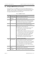
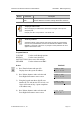
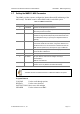
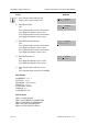
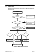
Table Of Contents
- Purpose
- Document Content and Organization
- Conventions
- Reference
- Revision History
- Symbols
- Caution
- Overview
- 1 Overview of Wireless LAN
- 2 Overview of OfficeServ 500 Wireless LAN
- 3 Components of OfficeServ 500 Wireless LAN
- 4 Specification of OfficeServ 500 Wireless LAN
- Hardware of OfficeServ 500
- Installation
- MMC Programming
- Maintenance
- WLAN (802.11b/DSSS) Specifications
- Antenna Beam Pattern of WBS24

CHAPTER 5. Maintenance OfficeServ 500 Wireless LAN Service Manual/Ed.00
Page 5-2
© SAMSUNG Electronics Co., Ltd.
Table 5.1 WBS24 LED Status and Meaning of the WBS24
LED Name Function Blue On Blue Off Blue Blinking
PWR Status of Power Supply Normal power
supply
No power supply -
WLAN Operating status of
wireless LAN
Normal operation
of wireless LAN
No operation of
wireless LAN
Data being
received and
transmitted via
wireless LAN
LAN Operation status of
LAN
Normal operation
of LAN
No operation of
LAN
Data being
received and
transmitted via
LAN
WLI Connection status with
the 8WLI
Normally
connected with
the 8WLI card
Not connected
with the 8WLI
card
Data being
received and
transmitted via the
8WLI card and the
DASL line
LD1 Indicating the B
channel in use
Refer to the table below
LD2 Indicating the B
channel in use
Table 5.2 Status of WBS24 LD1, LD2 LEDs
The number of B channels
being communicated
LED status of the LD1 LED status of the LD2
0 Blue LED Off Blue LED Off
One Blue LED Blinking Periodically Blue LED Off
Two Blue LED Off Blue LED Off
Three Blue LED Off Blue LED Blinking Periodically
Four Blue LED Off Blue LED Off
1.1.1 Booting Failure
When the WBS24 fails to boot up, it means that the flash memory with the program
is not functioning. All of the 5 LEDs, except the PWR, blink periodically at the same
time to inform the fault status. The flash memory might be broken when the process
of the WBS24 upgrade is interrupted, and the fault status can be removed using ‘the
upgrade using the network booting’ method.