
User's Manual
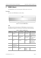
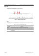
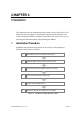
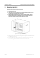
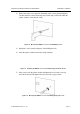
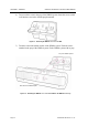
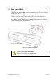
Table Of Contents
- Purpose
- Document Content and Organization
- Conventions
- Reference
- Revision History
- Symbols
- Caution
- Overview
- 1 Overview of Wireless LAN
- 2 Overview of OfficeServ 500 Wireless LAN
- 3 Components of OfficeServ 500 Wireless LAN
- 4 Specification of OfficeServ 500 Wireless LAN
- Hardware of OfficeServ 500
- Installation
- MMC Programming
- Maintenance
- WLAN (802.11b/DSSS) Specifications
- Antenna Beam Pattern of WBS24

OfficeServ 500 Wireless LAN Service Manual/Ed.00 CHAPTER 3. Installation
© SAMSUNG Electronics Co., Ltd. Page 3-5
2) Drill a hole at the ‘screw position’ illustrated in the <screw position diagram>.
The hole shall be at least 35mm deep and 5.5mm wide, which will enable the
plastic anchor to enter the hole easily.
Figure 3.4 Mounting the WBS24 on a Concrete Wall-Drilling a Hole
3) Detach the <screw position diagram> after drilling the hole.
4) Insert the plastic anchor into the hole using a hammer.
Figure 3.5 Mounting the WBS24 on a Concrete Wall-Inserting the Plastic Anchor
5) Insert a screw into the plastic anchor and tighten the screw with a cross-tip
screwdriver. Do not fully tighten the screw, but leave a gap of 5mm.
Figure 3.6 Mounting the WBS24 on a Concrete Wall-Tightening the Screw