
User's Manual
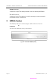
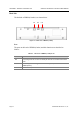
Table Of Contents
- Purpose
- Document Content and Organization
- Conventions
- Reference
- Revision History
- Symbols
- Caution
- Overview
- 1 Overview of Wireless LAN
- 2 Overview of OfficeServ 500 Wireless LAN
- 3 Components of OfficeServ 500 Wireless LAN
- 4 Specification of OfficeServ 500 Wireless LAN
- Hardware of OfficeServ 500
- Installation
- MMC Programming
- Maintenance
- WLAN (802.11b/DSSS) Specifications
- Antenna Beam Pattern of WBS24

OfficeServ 500 Wireless LAN Service Manual/Ed.00 CHAPTER 2. Hardware of OfficeServ 500
© SAMSUNG Electronics Co., Ltd. Page 2-3
LED
The LEDs are placed on the front side of WBS24(Combo) to show the status of
WBS24(Combo) equipment. The LED states are described in the following table.
Table 2.1 LED states of WBS24 (Combo)
LED Name Function Blue LED On Blue LED Off Blue LED Blinking
WLAN Wireless LAN is
operating
Wireless LAN is
normally operating
Wireless LAN
is not operating
Data is
transmitted/received
through wireless LAN.
LAN LAN is operating LAN is normally
operating
LAN is
normally not
operating
Data is
transmitted/received
through LAN.
WLI Connected with 8WLI Normally
connected with
8WLI
Not connected
with 8WLI
Data is
transmitted/received
through the 8WLI
card and DASL line.
LD1 Indicating the B
channel in use.
Refer to the Table below.
LD2 Indicating the B
channel in use.
Refer to the Table below.
PWR Power is on Power is normally
supplied.
Power is not
normally
supplied.
-
Table 2.2 LD1 and LD2 states of WBS24 (Combo)
B channel No. on busy States of LD1 States of LD2
0 Blue LED Off Blue LED Off
1 Blue LED blinking periodically Blue LED Off
2 Blue LED On Blue LED Off
3 Blue LED On Blue LED blinking periodically
4 Blue LED On Blue LED On
The status of WBS24(Combo)
Refer to ‘Chapter 5 Maintenance’ of this manual for how to inquire the status of
WBS24(Combo) through the LEDs in detail.