Offic e Se r v 5 0 0 Wire le ss LAN Se r vic e M a nua l Ed. 00 9. 2003.
COPYRIGHT This manual is proprietary to SAMSUNG Electronics Co., Ltd. and is protected by copyright. No information contained herein may be copied, translated, transcribed or duplicated for any commercial purposes or disclosed to third parties in any form without the prior written consent of SAMSUNG Electronics Co., Ltd. TRADEMARKS Product names mentioned in this document may be trademarks and/or registered trademarks of their respective companies.
INTRODUCTION Purpose This service description introduces WBS24, 8WLI card, and WIP-5000M mobile phone that provide the wireless LAN function of OfficeServ 500 System. This manual contains information on installation, troubleshooting method, and MMC setting method. Document Content and Organization This manual is composed of 5 chapters. Each chapter is summarized as follows : CHAPTER 1.
Introduction OfficeServ 500 Wireless LAN Service Manual/Ed.00 CHAPTER 5. Maintenance How to troubleshoot problems through LED states of WBS24 How to check the WBS24 status through a web browser How to upgrade the software of WBS24 How to upgrade the software of 8WLI ANNEX A. WLAN (802.11b/DSSS) Specifications Features and Specifications of the 802.11b/DSSS wireless LAN standard ANNEX B.
OfficeServ 500 Wireless LAN Service Manual/Ed.00 Introduction Reference OfficeServ 500 Installation Description Introduces information on how to install the OfficeServ 500 System. OfficeServ 500 Programming Description Introduces how to program MMC that sets up various functions of OfficeServ 500 System from a digital phone.
Introduction OfficeServ 500 Wireless LAN Service Manual/Ed.00 Regulatory Information - FCC Information This equipment has been tested and found to comply with limits for a class B digital device. Pursuant to Part 15 of the FCC Rules. These limits are designed to provide reasonable Protection against harmful interference in a residential installation.
SAFETY CONCERNS For product safety and correct operation, the following information must be given to the operator/user and shall be read before the installation and operation. Symbols Caution Indication of a general caution Restriction Indication for prohibiting an action for a product Instruction Indication for commanding a specifically required action © SAMSUNG Electronics Co., Ltd.
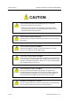
Safety Concerns OfficeServ 500 Wireless LAN Service Manual/Ed.00 Caution CAUTION Cautions against unpacking and assembling the product components - Do not give excessive shock on the product. - Check each connector and screw very carefully when reassembling after the components are unpacked once. The reassembled product shall not have any spaces between the housing and the base. Cautions against mounting the 8WLI card The 8WL card can be installed in the OfficeServ 500 System.
OfficeServ 500 Wireless LAN Service Manual/Ed.00 Introduction Cautions against handling the board When connecting a line cord after a board is dismantled, do not place a board near metal and conductive objects. Prevention of Electrostatic Hazards When handling an electric component, wear an anti-static wrist strap or discharge the electrostatics from your body by touching a grounded object periodically. © SAMSUNG Electronics Co., Ltd.
Safety Concerns OfficeServ 500 Wireless LAN Service Manual/Ed.00 This page is intentionally left blank. Page VIII © SAMSUNG Electronics Co., Ltd.
TABLE OF CONTENTS INTRODUCTION T Purpose ...................................................................................................................................I Document Content and Organization ......................................................................................I Conventions ............................................................................................................................II Reference .................................................................
Table of Contents OfficeServ 500 Wireless LAN Service Manual/Ed.00 CHAPTER 2. Hardware of OfficeServ 500 1 U 2 U 3 U 8WLI ................................................................................................................................... 2-1 U U U U U U U WBS24 (Combo)................................................................................................................ 2-2 U WBS24 (Basic) ................................................................................
OfficeServ 500 Wireless LAN Service Manual/Ed.00 2.4 2.5 2.6 2.7 U Setting the MMC848 WIP Lists .................................................................................4-11 Setting the MMC849 WLI REGIST .......................................................................... 4-12 Setting the MMC830 Ethernet Parameters ............................................................. 4-14 Setting the MMC831 MGI Parameters ....................................................................
Table of Contents OfficeServ 500 Wireless LAN Service Manual/Ed.00 LIST OF FIGURES Figure 1.1 Figure 1.2 Figure 1.3 Figure 1.4 Figure 1.5 Configuration Diagram of OfficeServ 500 Wireless LAN ............................ 1-4 8WLI Block Diagram ..................................................................................... 1-8 Block Diagram of WBS24 WBS24 (Combo) ............................................... 1-14 Block Diagram of WBS24 WBS24 (Basic) .................................................
OfficeServ 500 Wireless LAN Service Manual/Ed.00 Table of Contents Figure 5.13 Web screen for upgrading the WBS24 S/W (Firmware Upgrade Complete) ................................................................... 5-14 Figure 5.14 Web screen for inquiring the WBS24 S/W (Initial screen) .......................... 5-15 Figure 5.15 Upgrading the WBS24 S/W via the Network Booting (1) ........................... 5-16 Figure 5.16 Upgrading the WBS24 S/W via the Network Booting (2) ...........................
Table of Contents OfficeServ 500 Wireless LAN Service Manual/Ed.00 LIST OF TABLES Table 1.1 Table 1.2 Table 1.3 Table 1.4 Interrupt Information on 8WLI CPU............................................................... 1-9 General Specification of Wireless LAN ....................................................... 1-19 Specification of WBS24 (Combo/Basic) ...................................................... 1-19 Specification of WIP-5000M ...............................................................
CHAPTER 1 Overview This chapter describes the general introduction of wireless LAN, functions of OfficeServ 500 wireless LAN, components of OfficeServ 500 wireless LAN, and specifications for WBS24, 8WLI Card and WIP-5000M mobile phone. 1 Overview of Wireless LAN The LAN can be distinguished into two different kinds, wired LAN and wireless LAN, depending on the mobility and presence of stations.
CHAPTER 1.Overview 2 OfficeServ 500 Wireless LAN Service Manual/Ed.00 Overview of OfficeServ 500 Wireless LAN The OfficeServ 500 system, which is the key telephone system of Samsung, offers voice or data service in a wireless LAN and can simultaneously send/receive voice and data. The wireless LAN service is offered through WLAN Base Station 2.4 GHz(WBS24), which is an Access Point(AP) device.
OfficeServ 500 Wireless LAN Service Manual/Ed.00 CHAPTER 3. Installation The voice service is provided even in no-wired LAN environment. The quality of service(QoS) is guaranteed using the exclusive voice path. Since the OfficeServ 500 System supplies power remotely to the WBS24, no separate electric wiring work is needed. The transmission distance between the OfficeServ 500 System and the WBS24 is 600 meters, so the cell can be easily designed.
CHAPTER 1.Overview 3 OfficeServ 500 Wireless LAN Service Manual/Ed.00 Components of OfficeServ 500 Wireless LAN Review the configuration diagram of OfficeServ 500 System below and understand the equipment implementing the wireless LAN functions and their operational principles. Voice signal Data signal Data signal WIP-5000M WBS24(Basic) Internet LAN Ethernet 10/100BASE-T Voice signal Data signal Wireless VoIP phone Handover IEEE802.
OfficeServ 500 Wireless LAN Service Manual/Ed.00 CHAPTER 3. Installation Also, if the 10 M/100 Mbps LAN port, which is provided by the OfficeServ 500 System, is used, the application program like the PCMMC(PC for programming) uses can be used while connected to Ethernet.
CHAPTER 1.Overview OfficeServ 500 Wireless LAN Service Manual/Ed.00 The system programming can be done with the system-connected terminal or PC. Also, the system configuration can be changed easily according to the user’s requirements. Ease of System Scalability If the OfficeServ 500 System is used, there is no need to put in much effort and expenses to add new functions. For the OfficeServ -L System case, a maximum of 3 cabinets can be scaled up.
OfficeServ 500 Wireless LAN Service Manual/Ed.00 3.2 CHAPTER 3. Installation 8WLI 3.2.1 Overview The 8WLI card, a service board providing the wireless solution to the OfficeServ 500 System, provides the wired interface in between the OfficeServ 500 System and WBS24(WLAN Base Station 2.4 GHz), which is the wireless LAN’s AP(Access Point).
CHAPTER 1.Overview OfficeServ 500 Wireless LAN Service Manual/Ed.00 3.2.3 8WLI Block Introduces the block diagram of 8WLI card and the functions of each block. Signalling Data Comm. (16Kbps) 32Ch, Echo Canceller (ZL50232) HWx/HWR DASL DASL FWR CTL. HWx/HWR DASL DASL FWR CTL. DMC0 STL7052E SF_DTAC DASL DASL FWR CTL. CPLD EPM7064 Clock Generator OSC 16,384 TCXO DJT. 10m 600m DPRAM CY7C631 DASL DASL FWR CTL. DJT, DASL, DEK, DTK LINE INTERFACE CPU MC68302 DASL DASL FWR CTL.
OfficeServ 500 Wireless LAN Service Manual/Ed.00 CHAPTER 3. Installation Main Processor The main CPU used in the 8WLI is Motorola’s MC68000/MC68008 core series, which enhanced the communication function.
CHAPTER 1.Overview OfficeServ 500 Wireless LAN Service Manual/Ed.00 SRAM Two SRAMs of 256 Kbyte X 2 capacity are used, and they operate with the CPU on the 16 bits mode for transmitting/receiving data. The KM684000LT of SAMSUNG is used. Asynchronous Dual Port RAM The DPRAM is used for data transmission with the main board of OfficeServ 500 system. The components used for IPC(Inter-processor communication) are the CY7C13655NC of Cypress, and this can read/write 2Kbyte data at the same time.
OfficeServ 500 Wireless LAN Service Manual/Ed.00 CHAPTER 3. Installation Power Supply The power of WBS24 is supplied from the system using the remote power feeding method. So, -48V DC power of the system is supplied from the 8WLI to the WBS24 through the DASL transmission line. The transmission cable connected between the WBS24 and the system is composed of 4 strands grouped into 2 pairs.
CHAPTER 1.Overview OfficeServ 500 Wireless LAN Service Manual/Ed.00 3.3.3 Interface The WBS24(Combo) consists of wire processing part and wireless processing part. The wire processing part has two wire interfaces : ISDN BRI interface connected to OfficeServ 500 system and IEEE 802.3 Ethernet connected to LAN. The wireless processing part has 2.4 GHz frequency bandwidth of wireless LAN, which complies with the RF interface based on IEEE 802.11b standard.
OfficeServ 500 Wireless LAN Service Manual/Ed.00 CHAPTER 3. Installation 3.3.4 Application Specifications The WBS24(Combo) is designed to meet both specifications of wireless type and electromagnetic compatibility(EMC) as follows : Type Registration (Domestic Specification) Among different types of wireless equipment that use radio wave signals, the following equipment, available to the general public, shall be approved of its type.
CHAPTER 1.Overview OfficeServ 500 Wireless LAN Service Manual/Ed.00 3.3.5 WBS24 (Combo) Block The block diagram of WBS24(Combo) and functions for each block are as follows. Ethernet 10/100T Magnetic UART DASL_Int. Reset Ethernet I/F RJ-45 25MHz Xtal Voltage 3.3V Regular 1.8V DC/DC Power (Remote) -48V RJ-45 -48/+5, +3.3 5.0V DASL 2048NHz OSC DSP_Int PCMCIA I/F(EPD) 3.3V or 5.0V EPB BUS 8bits SDRAM BUS 32bits UART (D_Ch) PCM I/F DASL.Int PCMCIA Power Controller (3.
OfficeServ 500 Wireless LAN Service Manual/Ed.00 CHAPTER 3. Installation 3.4.3 Interface The WBS24(Basic) consists of wire processing part and wireless processing part. The wire processing part has a wire interfaces : IEEE 802.3 Ethernet connected to LAN. The wireless processing part has 2.4 GHz frequency bandwidth of wireless LAN, which complies with the RF interface based on IEEE 802.11b standard.
CHAPTER 1.Overview OfficeServ 500 Wireless LAN Service Manual/Ed.00 3) The power density supplied to the feeder of sending antenna shall be less than 10mW when it is measured based on 1 MHz of resolution bandwidth.
OfficeServ 500 Wireless LAN Service Manual/Ed.00 CHAPTER 3. Installation 3.4.5 WBS24 (Basic) Block The block diagram of WBS24(Basic) and functions for each block are as follows. Ethernet 10/100T Magnetic RJ-45 Reset Ethernet I/F 25MHz Xta -48V DC/DC Power (Remote) -48/+5, +3.3 Embedded CPU (NetARM Core *2) Regular (3.3V/5V Auto Switch) Input : 3.3V Output : 1.8V AC220/DC+5V SIO RS232C SDRAM 16M byte 3.3V or 5.0V PCMCIA Power Controller 1.8V SDRAM 3.
CHAPTER 1.Overview OfficeServ 500 Wireless LAN Service Manual/Ed.00 3.5.2 WIP-5000M Block Diagram Receiver CODEC Flash MEM BPF MPU Netergy PA IF/ MOD Graphic LCD MMI INTERFACE RF/IF Conv MIC Head Set Key-pad Battery Charging Cradle Vibrator PCMCIA CPLD BBP MAC F/ROM WLAN(802.11b) Part CPU, VoIP(SIP) Part User Interface Part Figure 1.
OfficeServ 500 Wireless LAN Service Manual/Ed.00 4 CHAPTER 3. Installation Specification of OfficeServ 500 Wireless LAN This section introduces the relevant specifications of OfficeServ 500 Wireless LAN. 4.1 Specification of Wireless LAN Table 1.
CHAPTER 1.Overview 4.3 OfficeServ 500 Wireless LAN Service Manual/Ed.00 Specification of WIP-5000M Table 1.4 Specification of WIP-5000M Category Specification Standard Interface Specification WLAN : 802.11b, VoIP : SIP Protocol RF frequency 2.412~2.462 GHz RF output power(EIRP) Maximum of 13dBm Transmission Protocols DSSS(Direct Sequence Spread Spectrum) Voice Codec G711/G729A/G723.1 Size 125(width)x45(length)x24(height) mm Weight About 95g Battery 3.
CHAPTER 2 Hardware of OfficeServ 500 This chapter examines the 8WLI card that provides the wireless LAN function of OfficeServ 500 the WBS24(Combo), WBS24(Basic)and the front/back sides of WIP5000M. Also, this chapter describes how to use each port and how to check the status of equipment through the LED indicators. 1 8WLI The 8WLI(Wireless LAN Interface) card shall be mounted on the OfficeServ 500 System, and this card is loaded with the wireless LAN function.
CHAPTER 2. Hardware of OfficeServ 500 OfficeServ 500 Wireless LAN Service Manual/Ed.00 Champ Connector Composed of 50 pins. This champ connector is used for connecting the WBS24. RS-232C Connector Composed of 9 pins. This connector is used for connecting the console terminal to download the software of 8WLI card. 2 WBS24 (Combo) The WBS24(Combo) is the AP for using the 2.4GHz wireless LAN service. U U Front Side The front side of WBS24(Combo) is shown below.
OfficeServ 500 Wireless LAN Service Manual/Ed.00 CHAPTER 2. Hardware of OfficeServ 500 LED The LEDs are placed on the front side of WBS24(Combo) to show the status of WBS24(Combo) equipment. The LED states are described in the following table. Table 2.1 LED states of WBS24 (Combo) LED Name WLAN Function Blue LED On Blue LED Off Blue LED Blinking Wireless LAN is Wireless LAN is Wireless LAN Data is operating normally operating is not operating transmitted/received through wireless LAN.
CHAPTER 2. Hardware of OfficeServ 500 OfficeServ 500 Wireless LAN Service Manual/Ed.00 Back Side The backside of WBS24(Combo) is as shown below. WLI SIO LAN Figure 2.3 Back side of WBS24 (Combo) Port The ports on the back of WBS24(Combo) and their functions are described as follows : Table 2.3 Functions of WBS24 (Combo) Ports LED Name WLI Functions Connecting the RJ-45 connector of twisted pair cable that is connected with the 8WLI card.
OfficeServ 500 Wireless LAN Service Manual/Ed.00 3 CHAPTER 2. Hardware of OfficeServ 500 WBS24 (Basic) The WBS24(Basic) is the AP for using the 2.4GHz wireless LAN service. Front Side The front side of WBS24(Basic) is shown below. WLAN LAN WLI LD1 LD2 PWR Figure 2.4 Front side of WBS24 (Basic) LED The LEDs are placed on the front side of WBS24(Basic) to show the status of WBS24(Basic) equipment. The LED states are described in the following table. Table 2.
CHAPTER 2. Hardware of OfficeServ 500 OfficeServ 500 Wireless LAN Service Manual/Ed.00 Back Side The backside of WBS24(Basic) is as shown below. DC IN 5V ○+ LAN SIO ○- Figure 2.5 Back side of WBS24 (Basic) Port The ports on the back of WBS24(Basic) and their functions are described as follows : Table 2.5 Functions of WBS24 (Basic) Ports LED Name Functions DC 5 V Used for local power supply. It is a spare part and not used usually.
CHAPTER 3 Installation This chapter describes the installation procedure for the wireless LAN device. This chapter describes procedures for mounting the 8WLI card to the OfficeServ 500 system, mounting the WBS24, setting the system DB for the wireless LAN service, registering the WIP mobile phone, and positioning the WBS24. 1 Installation Procedure Installation and configuration procedures for the wireless LAN equipment of OfficeServ 500 System are as follows.
CHAPTER 3. Installation 2 OfficeServ 500 Wireless LAN Service Manual/Ed.00 Mounting the 8WLI Mount the 8WLI following the below instructions. 1) Prepare the 8WLI card. 2) Turn off the power of the OfficeServ 500 System and detach the front cover of the OfficeServ 500 System using a screwdriver. 3) Mount the 8WLI card between slot 1 and slot 3 inside the cabinet. There are guardrails attached at the top and bottom of the slot to fasten the 8WLI card.
OfficeServ 500 Wireless LAN Service Manual/Ed.00 CHAPTER 3. Installation Figure 3.3 Mounting the 8WLI Card (2) Cautions against mounting the 8WLI card The 8WL card can be installed in the OfficeServ 500 System. Do not use this card on other systems. © SAMSUNG Electronics Co., Ltd.
CHAPTER 3. Installation 3 OfficeServ 500 Wireless LAN Service Manual/Ed.00 Mounting the WBS24 The WBS24 is classified into wall WBS24 and desk WBS24 depending on installation types. This section describes how to install a wall WBS24 or desk WBS24. 3.1 Wall Type of WBS24 A WBS24 can be installed on the wall to offer the wireless LAN service as described below : Required Tools Prepare the following tools in advance when mounting the WBS24 on a concrete wall.
OfficeServ 500 Wireless LAN Service Manual/Ed.00 CHAPTER 3. Installation 2) Drill a hole at the ‘screw position’ illustrated in the . The hole shall be at least 35mm deep and 5.5mm wide, which will enable the plastic anchor to enter the hole easily. Figure 3.4 Mounting the WBS24 on a Concrete Wall-Drilling a Hole 3) Detach the after drilling the hole. 4) Insert the plastic anchor into the hole using a hammer. Figure 3.
CHAPTER 3. Installation OfficeServ 500 Wireless LAN Service Manual/Ed.00 6) Two screw holes exist in the prop of the WBS24 system. Insert the screws on the wall into the screw holes. Pull the prop downward. Figure 3.7 Mounting the WBS24 on a Concrete Wall 7) Two holes exist at the bottom surface of the WBS24 system. The holes can be attached to the prop of the WBS24 system. Fit the WBS24 system with its prop. Prop of the WBS24 System Rear View of the WBS24 System Figure 3.
OfficeServ 500 Wireless LAN Service Manual/Ed.00 3.2 CHAPTER 3. Installation Desk Type of WBS24 The WBS24 can be installed on a desk by attaching its prop to the desk to offer the wireless LAN service. Two holes exist at the bottom surface of the WBS24 system.. The holes can be attached to the prop of the WBS24 system. Fit the WBS24 system with its prop as shown below : Put the WBS24 system on the desk carefully while preventing the system from being shaken or falling down.
CHAPTER 3. Installation 4 OfficeServ 500 Wireless LAN Service Manual/Ed.00 Connecting the 8WLI with the WBS24 When the cable with two twisted-pairs connecting the 8WLI and the WBS24 has the common characteristics, the OfficeServ 500 System’s wireless LAN offers good performance. Even when one of the two cable pairs is disconnected, the power will be supplied normally, since the WBS24 uses the phantom feeding method for power supply.
OfficeServ 500 Wireless LAN Service Manual/Ed.00 CHAPTER 3. Installation Connecting the Cable Connect the twisted-pair cable following the below instructions. As shown below, connect the Champ connector of the twisted-pair cable to the 8WLI’s Champ connector, and connect the RJ45 connector to the WBS24’s WLI port. Figure 3.11 Connecting the WBS24 with the 8WLI card © SAMSUNG Electronics Co., Ltd.
CHAPTER 3. Installation 5 OfficeServ 500 Wireless LAN Service Manual/Ed.00 Setting the System DB Before using the WIP-5000M terminal on the OfficeServ 500 System, appropriate values for the following items must be set in accordance with the operating environment, using the MMC program. 5.1 Setting the System KEY System KEY is used internally in the system.
OfficeServ 500 Wireless LAN Service Manual/Ed.00 5.4 CHAPTER 3. Installation Assigning a terminal IP Before registering a WIP500M terminal, an effective IP address shall be assigned to the WIP-5000M terminal using the MMC 848 program. This IP address shall be assigned for each terminal. Although this IP address may not be relevant when not using the data service, assign an effective IP address for later use of both voice and data services. 5.
CHAPTER 3. Installation 6 OfficeServ 500 Wireless LAN Service Manual/Ed.00 Registering/Clearing the WIP-5000M Terminal The WIP500M terminal must be registered to the system to be used in the OfficeServ 500 System Wireless LAN. This section introduces the procedures for registering and clearing the register of a terminal. 6.1 Registering a WIP-5000M Register a WIP-5000M terminal following the instructions below.
OfficeServ 500 Wireless LAN Service Manual/Ed.00 7 CHAPTER 3. Installation Positioning the WBS24 This section introduces the cell in where the WBS24 will be installed, and describes the data transmission rate affected by the terminal’s location. 7.1 Cell Overview The Figure 3.10 below illustrates the wireless transmission range of the WBS24.
CHAPTER 3. Installation OfficeServ 500 Wireless LAN Service Manual/Ed.00 Single Cell Generally, only one cell is configured for environments such as the wireless home terminal. Single cells are independent service areas, thus the cells do not affect one another. Configuration of single cells is illustrated in the Figure 3.11 below. Cell #1 Cell #2 Figure 3.
OfficeServ 500 Wireless LAN Service Manual/Ed.00 7.2 CHAPTER 3. Installation Data Transmission Rate on Terminal Location Data transmission rate and call quality are subject to the terminal’s location in an office. Refer to Figure 3.13 and Table 3.2 below. WBS24 A E C D B Figure 3.15 Data transmission rate on Station location Table 3.2 Data transmission rate on Station location No. 1 Station location WBS24↔Station Tx(Mbps) Rx(Mbps) 3.97 3.04 Note (close distance:20CM) 2 Test location ‘A’ 3.
CHAPTER 3. Installation OfficeServ 500 Wireless LAN Service Manual/Ed.00 This page is intentionally left blank. Page 3-16 © SAMSUNG Electronics Co., Ltd.
CHAPTER 4 MMC Programming This chapter describes the MMC programming procedures related to the wireless LAN function. Method of MMC programming Only the MMC programming procedures related to the wireless LAN are introduced in this chapter. Refer to the ‘OfficeServ 500 Programming Description’ for the overall system MMC programming procedures.
CHAPTER 4. MMC Programming 1.2 OfficeServ 500 Wireless LAN Service Manual/Ed.00 Programming Button The functions of the phone buttons for MMC programming are listed below. Table 4.1 Program buttons Button 1.
OfficeServ 500 Wireless LAN Service Manual/Ed.00 CHAPTER 4. MMC Programming 1.4 Programming Procedure This section describes the overall programming procedure. The procedure shall be read carefully and thoroughly understood. The programming procedure is described as follows. Program Procedure 1) Press the [TRSF] button, and enter 800. Display Screen PROGRAMMI NG MODE ENTER PGM I D: 2) Enter the PASSCODE (Operator or Engineer password).
CHAPTER 4. MMC Programming 2 OfficeServ 500 Wireless LAN Service Manual/Ed.00 Programming This section describes the MMC programming procedure related to the parameter modification of the 8WLI and the WBS24. The MMC related to the parameter modification of the 8WLI and the WBS24 are listed below. Table 4.2 Wireless LAN related MMC MMC No. 2.
OfficeServ 500 Wireless LAN Service Manual/Ed.00 CHAPTER 4. MMC Programming Defaults WLI WLI WLI WLI WLI WLI WLI WLI : : : : : : : : SYSTEM ID SYSTEM KEY 2 ND DNS 1ST DNS SYSTEM KEY 2 ND WBS IP CODEC LIST VERSION P P WBS24 0000 0. 0. 0. 0 0. 0. 0. 0 34568 168.208.144.10 G726 WBS001 : IP ADDR WBS001 : RF CH. 0. 0. 0.
CHAPTER 4. MMC Programming OfficeServ 500 Wireless LAN Service Manual/Ed.00 Program procedure 1) Press the [TRSF] button, and enter 845. Display Screen WL I : SYSTEM I D 0000 845: WL I PARA SEL ECT PROG I D 2) Press the [SPK] key to enter the select menu. When the cursor is at WLI, press the [UP & DOWN] button and select WLI or WBS1~254. 3) Press the Soft key and move to the SYSTEM ID. When the cursor is below SYSTEM ID, press the [UP & DOWN] key and select the setting menu for WLI or WBS24.
OfficeServ 500 Wireless LAN Service Manual/Ed.00 Select the voice codec. Select from the four, G711u, G711, G726, and G729 CODEC. Numbers are given from 1 to 4 based on priority. CHAPTER 4. MMC Programming WL I : CODEC L I ST CODEC 1 : G7 2 6 WBS0 0 1 : I P ADDR 5) Set the items below at the WBS24 menu. Register the WBS24 IP ADDRESS. 0. Register the WBS24 RF CHANNEL. 0. WBS0 0 1 : 0. 0 RF CH. 1 Displays the WBS24 status. WBS0 0 1 : STATUS OFF Displays the WBS24 VERSION.
CHAPTER 4. MMC Programming OfficeServ 500 Wireless LAN Service Manual/Ed.00 6) Set the items below at the menu . Register the RETRANS T1. The initial re-transmission time if no answer based on the RFC2543 specification. The range is 0~9900ms. Default is 500 ms. Register the RETRANS T2. The maximum re-transmission time if no answer based on the RFC2543 specification. The range is 0~9900ms. Default is 4000ms. Register the RETRANS T4. The time the User Agent Server waits after receiving the ACK message.
OfficeServ 500 Wireless LAN Service Manual/Ed.00 Register the STOP INVNR T. Before sending Cancel for the Invite Request, the User Agent shall wait for this amount of time. The range is 0~99900 ms. Default is 5000 ms. Register the GEN REQ T. After sending General Request, he User Agent shall wait for the Final Response for this amount of time. The range is 0~99900ms. Default is 5000 ms. Register the PROVIS TIME.
CHAPTER 4. MMC Programming OfficeServ 500 Wireless LAN Service Manual/Ed.00 Program Procedure 1) Press the [TRSF] button, and enter 846. Display Screen 846: WI P I NFO SEL ECT PROG I D 2) Press the [SPK] key to enter the select menu. When the cursor is at the phone number, press the [UP & DOWN] button and select the current phonenumber information. Press the Soft key and move to the information menu of each information menu, and select the setting menu.
OfficeServ 500 Wireless LAN Service Manual/Ed.00 CHAPTER 4. MMC Programming Related Programs MMC 847 MMC 848 MMC 849 2.3 WLI RESET WLI IP LIST WLI REGIST Resetting the MMC847 WIP This MMC is used for rebooting the 8WLI or the WBS24, by software or independently. This MMC is also used for initializing the WBS24 or verifying the current connection status of the WBS24. Program Procedure Display Screen 1) Press the [TRSF] button, and enter 847.
CHAPTER 4. MMC Programming OfficeServ 500 Wireless LAN Service Manual/Ed.00 Program Procedure Display Screen 1) Press the [TRSF] button, and enter 848.. 848: WL I L I STS SEL ECT PROG I D 2) Press the [SPK] key and enter the select menu. Press the Soft key to change the IP ADDRESS while assigning the IP ADDRESS. 3) Use the Soft key to position the cursor at an IP ADDRESS, and assign the IP ADDRESS by entering values of 0~255.
OfficeServ 500 Wireless LAN Service Manual/Ed.00 CHAPTER 4. MMC Programming Program Procedure Display Screen 1) Press the [TRSF] button, and press 849. 849: WL I REGI ST SEL ECT PROG I D 2) Press the [SPK] key to enter the select menu. Enter the PASSCODE to activate the register. ENTER PASSCODE 3) Select ENABLE to register the terminal to the REGISTER WLI. WL I 4) Select the WEP KEY setting when ENCRYPTION is selected.
CHAPTER 4. MMC Programming 2.6 OfficeServ 500 Wireless LAN Service Manual/Ed.00 Setting the MMC830 Ethernet Parameters To use the basic type of the WBS24, the system network and MGI should be set. This MMC provides a mean to configure the Internet Protocol(IP) addressing of the OfficeServ 500 system MCP2 card. This MMC must be utilized if there are ITP series phones and/or MGI cards used on the system. Table 4.
OfficeServ 500 Wireless LAN Service Manual/Ed.00 Number 08 Parameters CHAPTER 4. MMC Programming Description REMOTE M/A When system wants connect to remote M & A PC, system will be send ADDR to this IP address for connection message. Reserved for future use. Changing IP address/value When changing any IP address/value, listed below, three digits must be input for each(octet) field. Example) 192.168.1.
CHAPTER 4. MMC Programming OfficeServ 500 Wireless LAN Service Manual/Ed.00 5) Using the keypad enter three digit IP octet numbers IE 192 168 001 001 for 192.168.1.1 Cursor will return to Step 5 upon completion of system gateway entry. 6) Press Volume button to make selection and press Right Soft button to move cursor. 7) Press Volume button to make selection and press Right Soft button to store and move cursor. SYSTEM GATEWAY 192. 168. 001.
OfficeServ 500 Wireless LAN Service Manual/Ed.00 2.7 CHAPTER 4. MMC Programming Setting the MMC831 MGI Parameters This MMC provides a mean to configure the Internet Protocol(IP) addressing of the MGI card(s). This MMC must be utilized MGI card(s) used on the system. Table 4.4 MMC831 Parameters Number Parameters Description 0 IP ADDRESS Specifies the IP address for the MGI card. 1 GATEWAY Specifies the designated IP gateway address used for contacting IP devices beyond the local subnet.
CHAPTER 4. MMC Programming OfficeServ 500 Wireless LAN Service Manual/Ed.00 Action 1) Press Transfer button and enter 831 Display shows the first MGI card 2) Enter MGI number OR Press Volume button to make selection and press Right Soft button to move cursor Press Volume button to make selection and press Right Soft button to move cursor. 3) Enter MGI parameter number OR Press Volume button to make selection and press Right Soft button to move cursor.
CHAPTER 5 Maintenance This chapter describes how to solve problems via a LED status of WBS24, how to verify the WBS24 using a web browser and how to upgrade the WBS24 software. 1 Verifying the Status of WBS24 1.1 Status inquiry via the LED Status Indicators With the LED indicators on the front panel of the WBS24, it is possible to verify the WBS24 status. When power is supplied to the WBS24, booting is allowed about ten minutes later. At this time, booting is indicated as the LD2 LED blinks regularly.
CHAPTER 5. Maintenance OfficeServ 500 Wireless LAN Service Manual/Ed.00 Table 5.
OfficeServ 500 Wireless LAN Service Manual/Ed.00 CHAPTER 5. Maintenance 1.1.2 Troubleshooting The troubleshooting steps according to the LED status of WBS24 are explained in the following flowchart. POWER ON - Verify the system power NO PWR LED ON - Verify the 8WLI status, or 8WLI connection line YES - I f the same status continues after YES The other LEDs except the PWR LED blink periodically. resetting two or three times, the flash memory image is damaged. - Upgrade via the network.
CHAPTER 5. Maintenance 1.2 OfficeServ 500 Wireless LAN Service Manual/Ed.00 Status Inquiry via a Web Browser When the IP address of WBS24 is connected via a wired cable or wirelessly to the PC, the initialization screen will be displayed. Figure 5.2 Web screen for inquiring the WBS24 status (Initial screen) 1.2.1 Description on Main Menu 4 main menus are located on the left side of the screen. The functions of each menu are shown below. Table 5.
OfficeServ 500 Wireless LAN Service Manual/Ed.00 CHAPTER 5. Maintenance 1.2.2 Inquiry of Config & Status With the selected [Config & Status] menu, the established value and status regarding the LAN and the WLAN can be inquired. Figure 5.3 Web screen for inquiring the WBS24 status (Config & Status) Status items are shown below.
CHAPTER 5. Maintenance OfficeServ 500 Wireless LAN Service Manual/Ed.00 1.2.3 Upgrading S/W With the selected [Upgrade] menu, the WBS24 software can be upgraded. At the first time connection, the user name and password will be asked. Enter the user name and password by inquiring from the system manager. (Example : a user name and password are initially set as 'wlan’) Figure 5.4 Web screen for inquiring the WBS24 status (Screen for entering password) For the software upgrade, refer to ‘2.
OfficeServ 500 Wireless LAN Service Manual/Ed.00 CHAPTER 5. Maintenance 1.2.4 Restarting WBS24 By selecting the [Restart] menu, the WBS24 can be restarted. When connecting for the first time, the user name and password will be asked. Enter the user name and password by inquiring from the system manager.( Example : a user name and password are initially set as 'wlan’) When the screen as shown below is displayed, click the [Restart] button to restart the WBS24. Figure 5.
CHAPTER 5. Maintenance OfficeServ 500 Wireless LAN Service Manual/Ed.00 1.2.5 Inquiring Statistical Information of Block LAN With the selected [LAN Statistics] menu, statistical information on data transmitted and received through the WLAN and the Ethernet can be inquired. Two sub menus will be displayed, so the statistical information by each sub-menu can be inquired. Inquiry screen of Wilress LAN statistics Figure 5.
OfficeServ 500 Wireless LAN Service Manual/Ed.00 CHAPTER 5. Maintenance Inquiry screen of the Ethernet statistics Figure 5.7 Web screen for Inquiring the WBS24 Status (Ethernet statistics) © SAMSUNG Electronics Co., Ltd.
CHAPTER 5. Maintenance 2 OfficeServ 500 Wireless LAN Service Manual/Ed.00 Upgrading the WBS24 S/W WBS24 S/W is upgraded in the following two methods. Use the web browser screen Use the network booting It is recommended to use the web browser method that the setting is easy and the usage is simple.
OfficeServ 500 Wireless LAN Service Manual/Ed.00 CHAPTER 5. Maintenance Figure 5.8 Web screen for upgrading the WBS24 S/W (Initial screen) Cautions against the roaming of the WBS24 If the PC is roamed to another WBS24 while upgrading, the upgrade will be interrupted and the flash memory will not be functioning. Accordingly, locate the PC as close as possible from the WBS24. To prevent roaming to another WBS24, it is recommended that all of the WBS24 power should be turned off for safety.
CHAPTER 5. Maintenance OfficeServ 500 Wireless LAN Service Manual/Ed.00 3) If a user is authorized successfully, the following screen will show up. Click the [Indexing] button. Select the prepared upgrade file(.tar type) Figure 5.10 Web screen for inquiring the WBS24 S/W (Firmware upgrade) Page 5-12 © SAMSUNG Electronics Co., Ltd.
OfficeServ 500 Wireless LAN Service Manual/Ed.00 CHAPTER 5. Maintenance 4) Click the [Upgrade] menu when the following screen is displayed. At this time, click the [Upgrade] button only once. The upgrade is preceded. The required time may vary according to the WBS24 status, but it is about three or four minutes. Figure 5.11 Web screen for inquiring the WBS24 S/W (Click the [Upgrade] button) Figure 5.12 Web screen for inquiring the WBS24 S/W (In the process of upgrade) © SAMSUNG Electronics Co., Ltd.
CHAPTER 5. Maintenance OfficeServ 500 Wireless LAN Service Manual/Ed.00 5) When the upgrade is completed, the following screen will show up. The upgrade contents are not applied at this time, and it is applied when restarting the WBS24. If the upgrade contents are needed to apply immediately, click the [Restart] button and restart the WBS24. After restarting, verify the version on the web screen. Figure 5.
OfficeServ 500 Wireless LAN Service Manual/Ed.00 CHAPTER 5. Maintenance Figure 5.14 Web screen for inquiring the WBS24 S/W (Initial screen) Wireless Connections It is not necessary to move the PC to the front of the WBS24 for the wireless connections. 2) The subsequent procedure is as same as No.2 ~No.5 of ‘Upgrading the wireless connection.’ When several units of WBS24 are installed, upgrade according to the procedures as described above by connecting to the relevant IP address of the WBS24.
CHAPTER 5. Maintenance 2.2 OfficeServ 500 Wireless LAN Service Manual/Ed.00 Upgrading via the Network Booting This method is used to recover an error such as non-functioning flash memory. This method is impossible to upgrade wirelessly, but only through a wired LAN. If the WBS24 is connected with a wired LAN, it is possible to upgrade without any change on the WBS24. But if not the case, the wired LAN shall be connected between the WBS24 and the PC in order to upgrade the WBS24.
OfficeServ 500 Wireless LAN Service Manual/Ed.00 CHAPTER 5. Maintenance Then the following screen will show up. After entering the MAC Address, IP Address and File Name, click the [Update] button. " Enter the MAC address of AP where to receive the file from # Enter the IP that AP is to be assigned for $ Enter the pathe and name of the file that AP will receive, or select the file by clicking the browser at the botton % Click the Update button Figure 5.
CHAPTER 5. Maintenance OfficeServ 500 Wireless LAN Service Manual/Ed.00 3 Upgrading the 8WLI S/W 3.1 Connecting the Console Terminal to the 8WLI Card 1) In order to upgrade the 8WLI card software, either PC with the terminal emulation on, such as a console terminal, or an ASCII terminal like VT-100 and VT-220 types is used. When connecting the console terminal to the 8WLI card, the console cable with 9-pin RS-232C connector as shown below is used. Figure 5.
OfficeServ 500 Wireless LAN Service Manual/Ed.00 3.2 CHAPTER 5. Maintenance Configuring the Console Terminal The values of the console terminal to be used are configured as shown below. Emulation : compatible with VT-100/ANSI Bits per second : 9600 bps Stop bit : 1 Data bit : 8 Parity bit : None Flow control : None The method of setting the console terminal can be different according to the terminal type or the management system. The file(WLIROM.HEX, MWLIROM.
CHAPTER 5. Maintenance OfficeServ 500 Wireless LAN Service Manual/Ed.00 Upgrading a New Software The 8WLI card can upgrade the software by downloading WLIROM HEX file and MWLIROM.HEX file via the console terminal. After storing both files in the console terminal, download them following the method below. 1) When the 8WLI card is normally operated, the following message will show up. Click the [ENTER] key.
OfficeServ 500 Wireless LAN Service Manual/Ed.00 CHAPTER 5. Maintenance =========HEX FILE INFORMATION ====================== HEX FILE START ADDR = 0x00110000 HEX FILE END ADDR = 0x0013465D HEX FILE TOTAL ADDR = 0x0002465D =========== FLASH MEMORY WRITE START=============== STEP 1. SECTOR ERASE SUCCESS STEP 2. PROGRAM WRITE SUCCESS =========== FLASH MEMORY WRITE END =============== Please [R] key to Restart or [L] key to Loading Again !! 7) Enter ‘L’, and then the following menu will show up.
CHAPTER 5. Maintenance OfficeServ 500 Wireless LAN Service Manual/Ed.00 3.2.2 Loading the File with Qmodem 1) Exeute qmodem.exe on the DOS window. This description explains how to load a file if the installed qmodem version is ‘SST V3.1a’. If another qmodem version is used, refer to the relevant manual. 2) Click the [Alt+P] key to set the modem value. Then the window will show up. 3) Click the [ENTER] key, and check if the <8WLI> prompt is generated or not on the main window.
OfficeServ 500 Wireless LAN Service Manual/Ed.00 CHAPTER 5. Maintenance 7) Select the < A)Ascii > menu by clicking [A] button on the window. 8) Enter the path of the file to be uploaded. For instance, if the file to be uploaded is located as same as the qmodem file, enter the ‘.\WLIROM.HEX’. If the file to be uploaded is not located as same as the qmodem file, enter the file name as well as the whole path of the upload file.
CHAPTER 5. Maintenance OfficeServ 500 Wireless LAN Service Manual/Ed.00 13) Select [2] menu to load the WLIROM..HEX file. Then the following message will show up. Selected 1> Single- WLI HEX FILE Loading Please Start Loading !! 14) Perform No.6)~No.10) as shown above and upload the MWLIROM.HEX file. Select the MWLIROM.HEX file instead of the WLIROM.HEX file. After uploading the MWLIROM.HEX file, the following message will show up.
Annex A WLAN (802.11b/DSSS) Specifications This annex describes the features and specification of a 802.11b/DSSS standard, a wireless LAN standard. 1 Feature Comparison with Other Standards Table A.1 Feature Comparison with WLAN (802.11b/DSSS) Standards Payload Name of Used Frequency Standards IEEE802.11b Transmittance Speed 2400~2483.5 MHz 1/2/5.5/11 Mbps Modulation Way FHSS, (US, Canada, ETSI) BPSK, 2400~2497 MHz QPSK, (Japan) CCK(DSSS) Feature CSMA/CA IEEE802.
Annex A. WLAN(802.11b/DSSS) Specifications 2 OfficeServ 500 Wireless LAN Service Manual/Ed.00 Operating Frequency by Channel and Country Table A.2 Operating Frequency of WLAN (802.
OfficeServ 500 Wireless LAN Service Manual/Ed.00 Annex A. WLAN(802.11b/DSSS) Specifications 3 Definitions and Features by Layer 3.1 Physical Layer DSSS Physical Layer DSSS physical layer diffuses data to 11 bit Barker words before sending the data. 11 bit Barker words have 10.4 dB of processing gain that meets FCC Part 15.247. All clients use the same 11 bit Barker words. DSSS physical layer has a total of 14 channels and null-to-null bandwidth is 22 MHz. Frequency scope is from 2.400 MHz through 2.
Annex A. WLAN(802.11b/DSSS) Specifications 3.2 OfficeServ 500 Wireless LAN Service Manual/Ed.00 MAC Layer MAC layer supports both an ad-hoc network and a client/server infrastructure network. CSMA/CA are base on distributed coordination function(DCF) and uses random back off algorithm to prevent the layer from collide with other media. Point coordination function(PCF) is optional and is used for adjusting the priority of media.
OfficeServ 500 Wireless LAN Service Manual/Ed.00 3.3 Annex A. WLAN(802.11b/DSSS) Specifications Data Link/Network Layer The flexibility of network construction, a strength of wireless LAN is fully considered in IEEE802.11 and is expressed in network models. Network models defined in IEEE802.11 are categorized into an ad hoc network and Infra network. Ad Hoc Network The Ad hoc network consists of terminals only and is based on direct communication between terminals.
Annex A. WLAN(802.11b/DSSS) Specifications OfficeServ 500 Wireless LAN Service Manual/Ed.00 Wireless LAN provides terminal users with wireless communication services through AP as shown in below figure. User1 User2 User3 AP User4 AP Internet Server Figure A.2 Data Link/Network Layer of WLAN-Infra Network Model Annex A-6 © SAMSUNG Electronics Co., Ltd.
OfficeServ 500 Wireless LAN Service Manual/Ed.00 Annex A. WLAN(802.11b/DSSS) Specifications 4 WLAN Frame Structure 4.1 Short PLCP PPDU Frame Format Scrambled Zero’s ShortSYNC 58 bits Backward SFD ShortSFD 16 bits DBPSK SIGNAL 8 bits SERVICE 8 bits LENGTH 16 bits CRC 16 bits 2 Mbit/s ShortPLCP Preamble 72 bits at 1 Mbit/s ShortPLCP Header 48 bits at 2 Mbit/s PSDU Variable at 2, 5.5 or 11 Mbit/s 96μs PPDU Figure A.3 Short PLCP PPDU Frame Format of WLAN 4.
Annex A. WLAN(802.11b/DSSS) Specifications 5 OfficeServ 500 Wireless LAN Service Manual/Ed.00 Quality of Service (QoS) QoS refers to the capability of networks that reduces the traffic volume of networks or reserves some bandwidth. Network administrators provide their networks with QoS in many ways. QoS does not mean 100% assurance of bandwidth or 0 % of packet loss rate. However, QoS enables network administrators to send specific traffic much faster or reserve network bandwidth.
Annex B Antenna Beam Pattern of WBS24 This annex displays the beam pattern of WBS24 antenna in illustration. Figure B.1 Beam Pattern of WBS24 Antenna © SAMSUNG Electronics Co., Ltd.
Annex B. Antenna Beam Pattern of WBS24 OfficeServ 500 Wireless LAN Service Manual/Ed.00 This page is intentionally left blank. Annex B-2 © SAMSUNG Electronics Co., Ltd.
ABBREVIATION A AP Access Point BRI Basic Rate Interface DSP Digital Signal Processor DASL Digital Adapter for Subscriber Loops DSSS Direct Sequence Spread Spectrum ETSI European Telecommunications Standards Institute FCC Federal Communication Commission ISM Industrial Scientific and Medical IP Internet Protocol ISDN Integrated Services Digital Network LED Light Emitting Diode LAN Local Area Network MAC Media Access Control NIC Network Interface Card B D E F I L M N © SAMSUNG
Abbreviation OfficeServ 500 Wireless LAN Service Manual/Ed.
OfficeServ 500 Wireless LAN Se r vic e M a nua l ©2003 Samsung Electronics Co., Ltd. All rights reserved. Information in this document is proprietary to SAMSUNG Electronics Co., Ltd No information contained here may be copied, translated, transcribed or duplicated by any form without the prior written consent of SAMSUNG. Information in this document is subject to change without notice. Visit us at http://www.samsungnetwork.