S Class Signal Processors 4 INPUT 4 ZONE STEREO MIXER
Safety Instructions/Consignes de sécurité/Sicherheitsvorkehrungen/Instrucciones de seguridad WARNING: To reduce the risk of fire or electric shock, do not expose this unit to rain or moisture. To reduce the hazard of electrical shock, do not remove cover or back. No user serviceable parts inside. Please refer all servicing to qualified personnel.
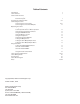
Table of Contents Introduction S zone Features Controls and Functions Front Panel Layout Rear Panel Layout Designing an Installation Plan Connecting the S zone Connecting the S zone Inputs Connecting the S zone Zone Outputs Operating the S zone Using the S zone Input Section Set the Input for Stereo or Mono operation Using the Zone Assignment switches Using the VOLUME Control Using the Monitor Section Using the headphone Controlling the Zone Outputs Setting the Output level Setting the Zone Output EQ For Vo
Introduction Congratulations on purchasing the Samson S zone, four channel, stereo zone mixer! Although this product is designed for easy operation, we suggest you take some time out first to go through these pages so you can fully understand how we’ve implemented a number of unique features. With proper care and adequate air circulation, your S zone will operate trouble free for many years. We recommend you record your serial number in the space provided below for future reference.
S zone Features The Samson S zone four-channel stereo zone mixer utilizes state-of-the-art, high quality audio circuit technology for precise tonal and level control. Here are some of the S zone’s main features: • The S zone has four stereo Input Channels with a Volume control, Stereo/Mono switch and our dedicated Zone assignment switches. • Channel 1 and Channel 2 inputs feature a high quality microphone pre-amp with phantom power allowing you to connect just about any dynamic or condenser microphone.
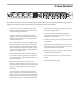
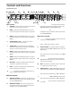
Controls and Functions Front Panel Layout � � � � � � � � �� �� �� � �� �� �� �� INPUT SECTION 1 VOLUME – Rotary control used to adjust the level of signal source connected to channel 1. 2 ZONE 1 – When the LED Backlit switch is pressed in, the switch lights red and the input is assigned to ZONE 1. 3 ZONE 2 – When the LED Backlit switch is pressed in, the switch lights green and the input is assigned to ZONE 2.
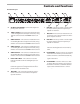
Controls and Functions Rear Panel Layout I MIC TRIM – The rotary control is used to adjust the input sensitivity of the microphone pre amplifier on channel 2. J MIC/LINE 1 – This connector includes the connection for a stereo line level and mono microphone input for channel 1. ZONE 2 OUTPUT – This connector includes the Zone 2 Left and Right balanced output connections, along with the connections for the REMOTE volume control.
Designing an Installation Plan Designing an Installation Plan If you are a professional installer, you’ll probably want to skip over this section, however if you are setting up your system for the first time this section can help make your installation a little bit easier. Now, take some time to consider where you need to have sound in your particular installation.
Designing an Installation Plan Using Passive Speakers If you are using passive (un-powered) speakers you need to first decide where you will place your power amplifier. If the speakers in a particular sound zone are less than 100 feet away you can locate your power amplifier in the same rack as the S zone and wire the speaker wires from the amplifier to your sound zone.
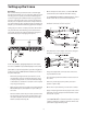
Setting up the S zone Quick Start We recommend that you take the time to read through this manual, and then, use it as a reference guide. If you are installing your first system you should read through the section “Designing an Installation Plan” on page 6 before you start connecting your S zone. If you’re a professional installer you can skip over that section and if you want to get started running some signals through your inputs and outputs, you can follow the following quick start example.
Setting up the S zone Quick Start - continued • Once you get a good level reading on the ZONE OUTPUT VU meter, you can begin to slowly raise the volume control on your active speakers or power amp. Note: The MIC TRIM level control allows you to set the best signal to noise level. Very simply put, this means the hottest mic level with the least amount of distortion. If the MIC TRIM is too low, the mic level may not be loud enough. If the MIC TRIM is set too high, the channel will distort.
Connecting the S zone Get Connected ! The S zone’s rear panel is where you will find all (except the headphone jack) of the input and output connections. The S zone provides four input channels that can accept up to four line level sources and two microphones and four output channels to feed the sound zones. The connections for these inputs and outputs are made via standard Euroblock connectors (the mating ends to connect to your wires have been included).
Connecting the S zone Connecting the S zone Zone Inputs - continued If you need to connect one or two microphones, along with more than two line level input sources, you can use the mic and line inputs for channel 1 and 2 at the same time. You should only do this if you need more than two line inputs. When you connect both the mic and line to the same input you will not be able to control the level of the two input sources individually.
Operating the S zone Using the S zone Input Section The S zone provides four stereo inputs that can also be set to accept mono signals. The input channels are where you will connect your sound sources like CD, DVD player, AV monitor output, paging mics or just about any other audio signal. Channel 1 and 2 also feature a high quality microphone input offering 58 dB of gain and phantom power for using condenser microphones.
Operating the S zone Using the Monitor Section The S zone features a unique monitor section located in the center of the unit allowing the operator or installer to listen to each of the zones in headphones or in the internal super speaker. The added convenience allows the installer or end user to monitor the program material that is playing in each zone from a single location in the building.
Operating the S zone Controlling the Zone Outputs The S zone has four output zones, which are controlled using the four ZONE output strips located on the right side of the front panel. Each Zone Output has its own level control, output meter and two-band equalizer. You can adjust the overall volume using the Level control and even apply some basic equalization to contour the frequency response of the speaker system when necessary.
Operating the S zone Using the Equalizer Each of the four Zone Outputs includes a two-band equalizer allowing individual equalization settings on each output channel. Located in the Zone Output section on the right side of the front panel, each output’s equalizer features LOW (BASS) and HIGH (TREBLE) controls. By using these controls to adjust the frequency response, you can to set an individual tonal contour curve for the speakers connected to each Zone Output.
Operating the S zone Using the Ducker The S zone allows you to set up a sophisticated music and paging system where the background music will automatically lower when an announcement is made. This automatic level control is known as Ducking. The S zone’s ducker can operate with either one or two microphones allowing two zone paging.
Operating the S zone Using the Ducker - continued You can set the S zone’s ducking matrix to seven settings. The diagram below shows the possible settings for using the DUCK ENABLE and MASTER switches. Follow the grid below and set the S zone Ducker switches to the positions that are best suited for your application.
S zone System Configurations Using the S zone with Active Speakers Using the S zone with Passive Speakers ® ® ® ® ® ® 18
The following example shows a typical installation in a small restaurant using the S zone to distribute audio for multimedia playback in the cocktail lounge, program music playback in the dining room and lobby and paging through the restaurant including the kitchen. For audio sources, a CD player is connected to the channel 4's line input and the audio from the LCD A/V monitor is connected to the line input on channel 3.
S zone Wiring Guide S zone Wiring Guide There are several ways to interface the S zone, depending on your exact monitoring set-up. Follow the cable diagrams below for connecting your monitor system.
S zone Specifications S zone Specifications Input Impedance: Mic Line Max Input Level Mic Line Maximum Gain Mic Line Output Level Output Impedance Balanced Unbalanced Max. S/N ratio THD CMRR: Phantom power 600Ω XLR balanced 22K Ω -14 dBV balanced +24 dBV 60 dB 26 dB +17 dBV max. 200 Ohms 100 Ohms 96 dB <.
S zone Block Diagram 22
Notes 23
Notes 24
Samson Technologies Corp. 575 Underhill Blvd. P.O. Box 9031 Syosset, NY 11791-9031 Phone: 1-800-3-SAMSON (1-800-372-6766) Fax: 516-364-3888 www.samsontech.