Introduction 1 MPL 1640 Features 1 Guided Tour 3 Overview 3 Channel 4 Main Section 6 Rear Panel 8 Connecting the MPL 1640 10 Balanced connectors 10 Unbalanced connectors 10 Mic connectors 10 Insert connectors 11 Setting Up and Using the MPL 1640 12 Setting the correct gain structure 12 Grounding Techniques 15 Using Bus 3/4 17 Using Pan 18 Using Equalization 19 Using the Auxiliary Sends and Returns 20 Using Channel Inserts 21 Using PFL Solo 22 Changing the MPL 1640 from Rack-mount to Tabletop 23 Applicat
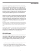
Introduction Congratulations on purchasing the Samson MPL 1640 mixer! In this manual, we’ll take you on a guided tour through all the features of this powerful and flexible device, and we’ll tell you how to get the most out of the MPL 1640 in your particular environment. If this is your first mixer, we’re confident that you’ll find the information in these pages valuable—read them carefully before proceeding further.
Introduction • 3 auxiliary sends and 3 stereo auxiliary returns (which can be used as 6 monophonic returns). Auxiliary return balance controls allow you to adjust the relative levels of the left and right inputs for each return. Aux send 1 is pre-fader and pre-equalizer, making it ideal for use as a headphone or monitor cue mix, while Aux sends 2 and 3 are post-fader and post-equalizer.
Guided Tour - Overview The following illustration shows an overview of the front panel of the MPL 1640: SAMSON MPL 1640 1 2 4 3 -10 -10 16 CHANNEL AUDIO MIXER -10 6 5 -10 7 -10 -10 9 8 -10 -10 11 10 -10 -10 12 -10 13 14 -10 -10 15 16 -10 -10 -10 0 +4 -50 INPUT TRIM 0 +4 -50 INPUT TRIM 0 +4 -50 INPUT TRIM 0 +4 -50 INPUT TRIM 0 +4 -50 INPUT TRIM 0 +4 -50 INPUT TRIM 0 +4 -50 INPUT TRIM 0 +4 -50 INPUT TRIM 0 +4 -50 INPUT TRIM 0 +4 -50 INPUT TRIM 0 +4 -50 INPUT TRIM 0
Guided Tour - Channel Let’s start our guided tour by examining the various controls provided by each channel: 1 -10 1 0 +4 -50 INPUT TRIM 0 -15 1: Input Trim (black) - This knob determines the input level of the connected mic or line signal. Continuously adjustable from +4 dB to -50 dB, the input trim is at unity gain (no boost or cut) when set to the 0 position. The input signal is boosted when the knob is turned to the right of 0 and attenuated when turned to the left of 0.
Guided Tour - Channel 6: Bus switch (gray) - When up, the channel’s signal is routed to the Main L/R faders (as described on page 7) and then on to the MPL 1640 Main Mix output jacks (as described on page 8). When pressed in, the channel’s signal is removed from the Main L/R output and is instead routed to the 3/4 Level knob (as described on page 6) and then to the 3L/4R output jacks (as described on page 8).
Guided Tour - Main Section MPL 1640 16 CHANNEL AUDIO MIXER STERE0 PFL -20 -10 -6 -3 0 +3 -20 -10 -6 -3 0 +3 +6 LEFT RIGHT PFL +6 1 POWER PHANTOM 2: Meter LEDs - These show the status of various conditions within the MPL 1640. The bottom left LED (labeled “PFL”) lights steadily red whenever one or more channels is soloed.
Guided Tour - Main Section 6: Headphones control (black) - This knob sets the level of the signal sent to the headphone jack (see #7 below). WARNING: To avoid possible damage to connected headphones (or, worse yet, to your ears!), always turn this all the way off (to the fully counterclockwise “0” position) before plugging in a pair of headphones—then raise the level slowly while listening. The Headphones control has no effect on the final Main Mix or Bus 3/4 output levels.
Guided Tour - Rear Panel 5 1 6 14 CAUTION ! RISK OF ELECTRIC SHOCK DO NOT OPEN 13 SERIAL NUMBER ASSEMBLED IN R.O.K. PHANTOM AVIS: XLR RISQUE DE CHOC ELECTRIQUE NE PAS OUVRIR. DO NOT EXPOSE THIS EQUIPMENT TO RAIN OR MOISTURE. 1 GND 2 + 3 - MAIN MIX OUT (BALANCED 600Ω + 4dB) ON CH 16 CH 15 CH 14 CH 13 CH 10 CH 11 CH 12 SAMSON MPL 1640 TIP RING SLEEVE 16 CHANNEL AUDIO MIXER TIP + RING SLEEVE GND SAMSON TECHNOLOGIES CORP., NEW YORK, U.S.A.
Guided Tour - Rear Panel 8: Bus Insert - Use these to insert an external in-line effects processor (such as outboard equalizer, compressor/limiter or noise gate) into the Bus 3/4 output in an “effects loop” configuration. These jacks accept 1/4" TRS plugs, with the ring carrying the send signal and the tip carrying the return signal. Normally, this will be connected to a Y-cable; see the “Connecting The MPL 1640” section on page 10 for more information and a wiring diagram.
Connecting The MPL 1640 The actual connections you’ll make to and from the MPL 1640 will vary according to the environment you use it in and the particular equipment you have. In the “Applications” sections at the conclusion of this manual (pages 24 - 27), you’ll find some suggested setups. Here we present a few basic rules concerning MPL 1640 connections that will apply in pretty much all situations: • In general, it’s best to make all connections with the MPL 1640 and all power amplifiers turned off.
Connecting The MPL 1640 • In addition to the sixteen monophonic input channels, there are three “hidden” (or at least not so obvious) stereo inputs to the MPL 1640; these are the Auxiliary returns.* Use these whenever you want to bring in a stereo signal that will not need to be equalized. Also bear in mind that the three stereo Auxiliary returns can also be used as six monophonic returns (with the Aux return Balance controls giving you the ability to adjust the relative levels of the left/right inputs).
Setting Up and Using the MPL 1640 Setting up your MPL 1640 is a simple procedure which takes only a few minutes: MAIN MIX OUT 1. Remove all packing materials (save them in case of need for future service) and decide where the unit is to be physically placed—it can be used on a tabletop or mounted in any standard 19” rack, requiring 8 rack spaces. (BALANCED 600Ω + 4dB) L SAMSON SERVO - 240 2.
Setting Up and Using the MPL 1640 f. If any condenser microphones are connected to the MPL 1640, turn on the Phantom switch.* Then turn on the MPL 1640—the Power LED in the meter section will light up. Finally, turn on the power amplifier. g. Play an instrument connected to one of the MPL 1640’s line inputs** and, while doing so, raise the corresponding channel fader to the “0” position.
Setting Up and Using the MPL 1640 l. The gain structure is now correctly set—you’ve optimized the level of all signals coming into and out of the MPL 1640, and the end result will be minimum noise and distortion and maximum clean sound.
Grounding Techniques Hum and buzz are the biggest enemies you face when interconnecting a large number of different pieces of equipment to a central audio mixer.
Grounding Techniques If you’re using the MPL 1640 in a fixed location such as a recording studio, you may want to invest the time and money into creating a star ground network. This is by far the best technique for avoiding grounding problems. It involves using a formidable ground source such as a cold water pipe or a copper spike driven into the earth.
Using Bus 3/4 In addition to the Main Mix stereo output, the MPL 1640 provides two independent bus outputs (Bus 3/4).* A “bus” is simply a pathway through which a signal can be routed. The provision of these secondary outputs makes it possible for you to create two mixes simultaneously, so that some channels send signal to the Main Mix output jacks (via the Main L/R faders) while other channels send signal to the Bus 3 and 4 output jacks.
Using Pan R L PAN The final Main output of the MPL 1640 is stereo—that is, there are two discrete Main Mix output jacks, labeled “left” and “right,” which will normally route signal (via a power amplifier) to two discrete speakers.* Because of this, you will usually be working with a stereo field that ranges from hard left to hard right. The Pan control in each channel allows you to place each individual sound at any point within this left-right field, while keeping the overall level constant.
Using Equalization One of the most exciting aspects to using a mixer such as the MPL 1640 is having the ability to shape a sound, using a process called equalization. But there are few areas of sound engineering more misunderstood than equalization, and, just as good EQ can really help a sound, bad EQ can really hurt it, so read on... Every naturally occurring sound consists of a broad range of pitches, or frequencies, combined together in a unique way.
Using the Auxiliary Sends and Returns The MPL 1640’s system of Auxiliary sends allow you to combine the signal from multiple channels and send the resulting mix to external devices such as effects processors. When an Aux send knob is at the “0” position, the signal is routed with unity gain (that is, no boost or attenuation). As it is turned clockwise from the 0 position, the signal is boosted; as it is turned counterclockwise from the 0 position, it is attenuated.
Using Channel Inserts In addition to using Auxiliary sends and returns to access outboard devices, the MPL 1640 also provides channel inserts for input channels 1 - 12 as well as for the Main Mix and Bus 3/4 outputs. Channel inserts should be used when you want to affect just one signal, as opposed to signal from several channels—most often, this will be for dynamic processing purposes (such as outboard equalization, compression/limiting, or noise gating).
Using PFL Solo OFF The MPL 1640 provides PFL (Pre-Fade Listen) solo switches for each of its sixteen input channels. The main function of PFL is to allow you to check that a signal is actually arriving at a particular input. When a PFL(solo) switch is pressed, the pre-fader (but post-EQ) signal of that channel alone is routed to the headphone output and to the meter.
Changing the MPL 1640 from Rack-mount to Tabletop The diagrams below show the steps required to convert the MPL 1640 from rack-mount to tabletop usage or vice-versa. CAUTION: These servicing instructions are for use by qualified personnel only. Refer all servicing to qualified service personnel.
Applications Here are four suggested applications for the MPL 1640; bear in mind that your particular circumstance may dictate changes in these suggested signal connections and routings. Application 1 - Using the MPL 1640 as a main live mixer The main connections here involve routing the MPL 1640’s Main Mix output to the input of a power amplifier, and, from there, to PA speakers. Microphones and line level signals are connected to various channel inputs.
Applications Application 2 - Using the MPL 1640 as an onstage monitor mixer Here, the MPL 1640 is receiving signal into its line inputs from the direct channel outputs of a main live mixer. Its Main Mix output is connected to an amplifier and onstage monitors, and the Main Mix inserts are connected to a graphic equalizer. This allows the overall mix to be adjusted in order to eliminate feedback and ringing problems.
Applications Application 3 - Using the MPL 1640 as a keyboard submixer Here, various keyboards and MIDI tone generators are connected to various line inputs of the MPL 1640. Signal processors are connected to Aux sends and returns and to channel inserts as required. The Main Mix output is routed to stereo input channels of a live performance or recording mixing console, with the performer having complete control over the blend of signals being provided to the sound engineer.
Applications Application 4 - Using the MPL 1640 as a recording mixer You can also use the MPL 1640 as a recording mixer when making simple recordings (for example, when recording a rehearsal or practice session direct to open-reel two-track, cassette, or DAT recorder). Microphones and line level signals are connected to various channel inputs. Signal processors are connected to Aux sends and returns and to channel inserts as required.
Appendix A: Changing the MPL 1640 Voltage Following are step-by-step instructions for changing the mains voltage of the MPL 1640. WARNING: Before carrying out this operation, remove the power cord! 110 110 220 1: Insert a small screwdriver into the hook beneath the fuse sled and pull it out from its retaining clip. Hold the hook with your fingers and gently pull the sled out. 2: Remove fuse sled. 3: Use a small pair of needlenose pliers to gently pull out the mains jumper.
INSERT LINE INPUT MIC INPUT 3 AUX RETURN 1 2 29 GND ++8V +15V -15V PHANTOM POWER LEVEL MID HIGH POWER SUPPLY CH FADER PAN RLY FUSE AC INLET POWER SW RETURN 2 -------3 BALANCE CH2 -------CH16 3 - BAND EQUALIZER LOW CLIP LED AUX 2 AUX 1 AC INPUT 120V/50,60 HZ PFL LED PFL SW BUS SELECTOR SW AUX 3 A A A U U U X X X 1 2 3 M M P A A F I I L N N R L R P F L L 3 L 4 R + G 1 N 5 D V _ 1 5 V R L R L R L 3L/4R VR AUX 3 AUX 2 AUX 1 R HEADPHONE VR L R OUTPUT L OUTPUT H
Specifications Normal Frequency Response Mic/Line to Main ± 1 dB (Trim @ min, output @ 0 dB, In/Out fader @ center position) Aux Return to Main ± 1 dB (Return VR @ “0” position, Main fader @ center position, output @ 0 dB) Limit 10 Hz - 45 kHz 20 Hz - 20 kHz 11 Hz - 26 kHz 20 Hz - 20 kHz Total Harmonic Distortion (Output 600 ohm balanced) Line to Main Out (Trim @ min, output @ 0 dB, In/Out fader @ center position, 1 kHz, with 80 kHz LPF) Line to Aux Send 0.016% 0.05% 0.016% 0.
Specifications Maximum Input Level (±3 dB) Ch Input Mic Ch Input Line +14 dB +24 dB Channel fader range +15 dB to -80 dB Aux send gain range +10 dB to -75 dB Input Channel Equalization (± 2 dB) High (10 kHz) Mid (800 Hz) Low (80 Hz) ± 15 dB ± 12 dB ± 15 dB Dimensions (W x D x H) 482 x 373 x 112 mm 19 x 14.7 x 4.4 in Weight Power Requirements Power Consumption 7 kg • 15.
Produced by On The Right Wavelength for Samson Technologies Corp. Copyright 1994, Samson Technologies Corp. Printed August 1994 Samson Technologies Corp.