Introduction 1 MPL 1502 Features 1 Guided Tour 3 Overview 3 Mono and Stereo Channels 4 Main Section 6 Rear Panel 8 Connecting The MPL 1502 - General Suggestions 10 Setting Up and Using the MPL 1502 13 Setting the Correct Gain Structure 14 Grounding Techniques 16 Using Pan/Balance 18 Using Equalization 19 Using Aux Sends and Returns 20 Using Channel Inserts 21 Applications Notes 22 Using The MPL 1502 As A Main Live Mixer 22 Using The MPL 1502 As A Monitor Mixer 23 Using The MPL 1502 As A Keyboard Submixer
Introduction Congratulations on purchasing the Samson MPL 1502 stereo mixer! Although this unit is designed for easy operation, we suggest you first take some time to go through these pages so you can fully understand how we’ve implemented a number of unique features. In this manual, we’ll provide you with an overview of the MPL 1502 features, followed by a guided tour of its front and rear panels.
Introduction • Independent 3-band equalization for each channel, with 15 dB of cut or boost for low (80 Hz) and high (10 kHz) frequencies, and 12 dB of cut or boost for the mid-range (800 Hz) frequency. • Constant level pan controls for placing each monophonic channel in the leftright stereo spectrum, as well as balance controls for each stereo channel and Aux return that allow you to blend the relative levels of stereo inputs.
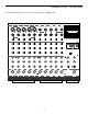
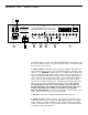
Guided Tour - Overview The following illustration shows an overview of the front panel of the MPL 1502: 1 2 3 5 4 6/7 8/9 10 / 11 12 / 13 14 / 15 LEFT/MONO LEFT/MONO LEFT/MONO LEFT/MONO LEFT/MONO MIC INPUT (BALANCED -50dB TO +4dB) 2 1 2 3 2 1 2 1 1 3 3 3 3 2 1 SAMSON LINE INPUT (BALANCED 10KΩ -30dB TO +4dB) LINE INPUT (BALANCED 10KΩ -40dB TO +4dB 10 0 0 +4 -50 0 +4 -50 0 +4 -50 RIGHT RIGHT RIGHT 10 10 10 10 0 0 +4 RIGHT 10 10 10 10 -50 +4 -50 0 0 +
Guided Tour - Mono and Stereo Channels 1 2 1 1 3 2 1: Mic inputs (1 - 5) - Provided in monophonic channels only. Use these electronically balanced XLR jacks to connect microphones to any of the MPL 1502’s five mono channels (channels 1 - 5). These are intended to accept signal from low-level, low-impedance mics but can also be used for signal from other sources (such as direct injection boxes) if the channel’s Trim control is turned down.
Guided Tour - Mono and Stereo Channels 6: Pan (white) - Provided in mono channels only. This knob allows you to place the input signal anywhere in the left-right stereo spectrum, while keeping the overall signal level constant. When the knob is placed at its center (detented) position, the signal is sent equally to both left and right outputs.
Guided Tour - Main Section MPL 1502 15 CHANNEL STEREO MIXER 1 LEFT -20 -10 -6 -2 -20 -10 -6 -2 0 +2 +6 0 +2 +6 RIGHT PHANTOM POWER 2 TAPE IN ON 3 OFF CHANNEL 14 / 15 0 −∞ +20 AUX 1 LEVEL L R BALANCE 4 5 0 −∞ L +20 AUX 2 LEVEL R BALANCE 6 7 0 10 HEADPHONE LEVEL 0 −∞ 8 +15 MAIN 1: Meter - This seven-segment bar meter shows the continuous output level of the main stereo output.
Guided Tour - Main Section 4: Stereo Auxiliary Return Level (gray) - These knobs determine the input level of signal arriving via the MPL 1502’s two stereo Auxiliary returns. Each return is at unity gain (no boost or attenuation) when set to the “0” (2 o’clock) position. The input signal is boosted when the knob is turned to the right of “0” and attenuated when turned to the left of “0.
Guided Tour - Rear Panel 1 2 POWER PHANTOM AVIS: ON RISQUE DE CHOC ELECTRIQUE NE PAS OUVRIR DO NOT EXPOSE THIS EQUIPMENT TO RAIN OR MOISTURE OFF RIGHT 0.3A/250V(115V) 0.15A/250V(230V) CAUTION RISK OF ELECTRIC SHOCK DO NOT OPEN SAMSON TECHNOLOGIES CORP.
Guided Tour - Rear Panel 5: Main out (L, R) - These are the MPL 1502’s main outputs. You’ll usually use these to connect the MPL 1502 to a power amp and speakers. The Main out jacks are electronically balanced, so you should use balanced three-conductor cabling and TRS plugs wherever possible (unbalanced two-conductor plugs can also be inserted into these outputs, but you’ll get better signal quality and less outside noise and hum if you use balanced lines).
Connecting The MPL 1502 - General Suggestions The actual connections you’ll make to and from the MPL 1502 will vary according to the environment you use it in and the particular equipment you have. In the “MPL 1502 Applications” sections at the rear of this manual, you’ll find some suggested setups. Here are a few basic rules concerning MPL 1502 connections that will apply in most situations: • In general, it’s best to make all connections with the MPL 1502 and any connected power amplifiers turned off.
Connecting The MPL 1502 - General Suggestions • For single-fader control over a pair of matched signals (i.e. the left-right outputs of a stereo effects processor, keyboard, drum machine, tone generator, CD player, or tape recorder), use the MPL 1502’s stereo input channels (6/7, 8/9, 10/11, 12/13, and 14/15). The Balance control in these channels will allow you to adjust the relative levels of the two inputs, and you can also equalize the stereo signal, with the same EQ settings applied to both inputs.
Connecting The MPL 1502 - General Suggestions • Signals that are likely to require “in-line” processing (such as compression/limiting or expansion/noise gating) should be connected to channels 1 - 5, since these channels provide an insert connection.
Setting Up and Using The MPL 1502 Setting up your MPL 1502 is a simple procedure which takes only a few minutes: 1. Remove all packing materials (save them in case of need for future service) and decide where the unit is to be physically placed—it can be used on a tabletop or optionally mounted in any standard 19” rack, requiring six rack spaces. 2. Before even plugging the unit into an AC socket, begin by connecting the MPL 1502 main outputs into a power amp and the amp into loudspeakers.
Setting the Correct Gain Structure You’re now ready to establish the correct gain structure—the key to getting the best performance from the MPL 1502, or from any mixer, for that matter. This is a simple procedure that ensures optimum input and output levels so that no unnecessary noise (caused by too low a signal) or overload distortion (caused by too high a signal) is created. Here’s a step-by-step description of how to do so: a.
Setting the Correct Gain Structure j. The procedure for setting optimum microphone levels is virtually identical; sing or speak into the mic at the level you expect to use in performance while slowly raising the gain control for that channel to its center detented “0” position. Then carefully adjust the input trim control for that channel while watching the meter, until the “0” segment lights frequently and the “+2” segment lights only occasionally.
Grounding Techniques Hum and buzz are the biggest enemies you face when interconnecting a large number of different pieces of equipment to a central audio mixer.
Grounding Techniques If you’re using the MPL 1502 in a fixed location such as a recording studio, you may want to invest the time and money into creating a star ground network. This is by far the best technique for avoiding grounding problems. It involves using a formidable ground source such as a cold water pipe or a copper spike driven into the earth.
Using Pan/Balance L R PAN L R BALANCE The final Main output of the MPL 1502 is stereo—that is, there are two discrete output jacks, labeled “left” and “right,” which will normally be routed to two discrete speakers.* Because of this, you will usually be working with a stereo field that ranges from hard left to hard right.
Using Equalization One of the most exciting aspects of using a mixer such as the MPL 1502 is the ability to shape a sound, using a process called equalization. But there are few areas of sound engineering more misunderstood than equalization, and, just as good EQ can really help a sound, bad EQ can really hurt it, so read on... 0 Every naturally occurring sound consists of a broad range of pitches, or frequencies, combined together in a unique way.
Using Aux Sends and Returns The MPL 1502’s two Auxiliary sends allow you to combine the signal from multiple channels and send the resulting mix to external devices such as effects processors. When an Aux send knob is at the “0” position, the signal is routed with unity gain (that is, no boost or attenuation). As it is turned clockwise from the 0 position, the signal is boosted; as it is turned counterclockwise from the 0 position, it is attenuated.
Using Channel Inserts In addition to using Auxiliary sends and returns to access outboard devices, the MPL 1502 also provides channel inserts for the first five (mono) input channels. These should be used when you want to affect just one channel’s signal, as opposed to signal from several channels—most often, this will be for dynamic processing purposes (such as outboard equalization, compression/limiting, or noise gating).
Applications Here are four suggested applications for the MPL 1502; bear in mind that your particular circumstance may dictate changes in these suggested signal connections and routings. Application 1 - Using The MPL 1502 As A Main Live Mixer The main connections here involve routing the MPL 1502’s Main output to the input of a power amplifier, and, from there, to PA speakers.
Applications Application 2 - Using The MPL 1502 As An Onstage Monitor Mixer Here, the MPL 1502 is receiving monophonic signal into its line inputs from the direct channel outputs of a main live mixer. Its Main output is connected to an outboard signal processor (typically an equalizer) prior to being routed to an amplifier and onstage monitors. This allows the overall mix to be adjusted in order to eliminate feedback and ringing problems.
Applications Application 3 - Using The MPL 1502 As A Keyboard Submixer Here, various keyboards and MIDI tone generators are connected to the mono and stereo line inputs of the MPL 1502. Signal processors are connected to Aux sends and returns and to channel inserts as required. The Main output can then be routed to a stereo input channel of a live performance or recording mixing console, with the performer having complete control over the blend of signals being provided to the sound engineer.
Applications Application 4 - Using The MPL 1502 For Recording You can also use the MPL 1502 for making simple recordings—for example, when recording a rehearsal or practice session direct to open-reel two-track, cassette, or DAT recorder. Connect the MPL 1502 tape outputs to the inputs of the two-track tape recorder, and connect the Main outputs to a power amplifier driving the control room speakers. The two tape recorder outputs are then returned to the MPL 1502 tape inputs.
Specifications 1. Frequency Response (0 dB = 1.0 V RMS) 17 Hz to 30 kHz ± 1.5 dB at +4 dB 2. Equivalent Input Noise Ch. 1 - Ch. 5 Mic input Ch. 1 - Ch. 15 Line input 3. THD+N (unity gain, 20 Hz - 20 kHz) 4. Input Level Ch. 1 - Ch. 5 Mic input Ch. 1 - Ch. 15 Line input Aux return 1 - 2 5. Maximum Input Level Ch. 1 - Ch. 5 Mic input Ch. 1 - Ch. 15 Line input 6. Trim gain range -128 dB (A filter, 150 Ω shorted) -131 dB (A filter, input shorted) Less than 0.