0 10 0 0 10 0 10 10 CONTROL ROOM MATRIX A U D I O C Class Signal Processors SAMSON
Safety Instructions Caution: To reduce the hazard of electrical shock, do not remove cover or back. CAUTION FOR CONTINUED PROTECTION AGAINST RISK OF FIRE, REPLACE ONLY WITH SAME TYPE FUSE ATTENTION No user serviceable parts inside. Please refer all servicing to qualified personnel.
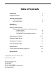
Table of Contents Introduction 2 C•control Features 3 Controls and Functions Front Panel Layout Rear Panel Layout 4 5 Quick Start Quick Set-up 6-7 Setting up the C•control Connecting Stereo Recorders and Sound Sources C•control Inputs C•control Outputs Connecting Line Level Speaker Outputs 8 9 9 Operating the C•control 11-14 C•control Typical Set-up 15 Stacking the C•control 16 C•control Wiring Guide 17 Specifications 18-19 C•class Dual Rack Adaptor (Optional) 20 Block Diagram 21 Copyr
Introduction Congratulations on purchasing the C control, Control Room Matrix by Samson Audio! The C control is a compact, high-quality device that provides the extensive control room monitoring features previously only found in expensive large format recording consoles. The C control is the perfect solution for interfacing all your stereo line sources including mixers, hard-disk recorders, 2-tracks, along with multiple sets control room monitors.
C•control Features SAMSON 0 10 0 10 0 10 0 10 The Samson C•control headphone amplifier utilizes the latest technology in gain management design. Here are some of it’s features: • Speaker and input source selector providing a convenient centralized point for routing and listening to stereo sources over various monitor speakers. • 3-way line level speaker selector providing A/B or A/B plus C switching.
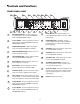
Controls and Functions FRONT PANEL LAYOUT 1 2 4 3 SOURCE 6 5 7 9 8 TALKBACK CONTROL ROOM DESTINATION SAMSON OL +6 MIX 2TK A 0 0 2TK B 2TK C MUTE 10 TALK TO CUE DIM HEADPHONE VOLUME -6 0 10 0 VOLUME SPK B VOLUME SPEAKER A SPEAKER B -18 0 10 10 TALKBACK LEVEL SUB TALK TO 2TK -30 L R LEVEL 10 11 12 13 HEADPHONE 14 15 16 SPEAKER C 17 MIC MONO 18 CONTROL ROOM MATRIX 19 1 MIX SOURCE SWITCH - Used to assign the main MIX input to the C controls SPEAKER, C
Controls and Functions REAR PANEL LAYOUT + - A DC INLET - The included AC/DC power supply is connected here. B REMOTE TALK - 1/4-inch phone connector used to connect external TALKBACK switch. C EXTERNAL CUE - Stereo output on two 1/4-inch balanced phone connectors for sending C control left and right mix to a headphone amplifier. D SPEAKER C - Stereo RCA outputs for connecting monitor power amplifier or powered monitors. Also can be used to connect an external powered subwoofer.
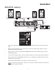
Quick Start QUICK SET-UP Setting up your C control is a simple procedure, which takes only a few minutes. There are many ways to interface the C control with various recording set-ups, so take some time to decide which audio devices you want to connect. The following section shows a simple set-up for a typical recording studio with an analog console and two sets of powered studio monitors.
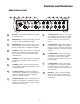
Quick Start QUICK SET-UP - Continued ® ® ® SIGNAL FLOW SIGNAL FLOW SAMSON POWER AC IN 18V 1A EXT CUE SPK B SPK C SPK A 2TK B 2TK A 2TK C 2TK B 2TK A MIX IN L L BALANCED + 2TK C L TALKBACK REMOTE SWITCH BALANCED BALANCED BALANCED BALANCED BALANCED BALANCED LINE INPUTS SIGNAL FLOW SIGNAL FLOW SIGNAL FLOW SIGNAL FLOW ® LINE OUTPUTS - 500mA R R R OUTPUT INPUT SIGNAL FLOW MIX OUTPUTS MIC/LINE 1 MIC/LINE 2 MIC/LINE 3/4 MASTER SECTION MIC/LINE 5/6 LEFT LEFT/MONO AUX
Setting-Up the C•control Connecting Stereo Recorders and Sound Sources C control Inputs The C control features four 2-track /Stereo inputs for connecting a variety of sounds sources including the output of the main mixing console or computer sound card, a DAT recorder, Open Reel Half-track (dust them off, they still sound great), Cassette recorder, CD player, MIDI workstation or sub mixers to name some. Each of the C controls stereo inputs can be turned on or off from the front panel assign switches.
Setting-up the C•control C control 2-Track Line Outputs The C control features three 2-track /Stereo outputs allowing you to connect the inputs of a variety of recording devices such as DAT recorders, Open Reel Half-tracks, Cassette recorders or CD players/burners. The signal that is assigned in the C controls Source section is always present at all the 2-track outputs, and is always at full strength and not affected by the Control Room level knob.
Setting-up the C•control 8 Speaker A The Speaker A outputs are balanced, 1/4-inch, TRS (Tip/ Ring/ Sleeve) phone connectors which output a +4dB line level signal. You can connect to an active studio monitor or power amplifier here. IMPORTANT NOTE: In order to maintain the best gain structure and signal to noise ratio, we highly recommend that only balanced cables be used on the SPEAKER A outputs. For detailed balanced cable wiring diagrams, please see page 17 in this manual.
Operating the C•control Operating the C Control Once you have connected your stereo recorders, stereo sound sources and studio monitor speakers you can begin to use, and enjoy the powerful features of the C control. The following section will take you through the operation of the C control’s switches, control knobs and operating functions. Controls and Functions SAMSON 14 POWER switch Use the POWER switch to turn the C control on and off.
Operating the C•control Using the Headphone Amplifier The C control includes an internal headphone amplifier for monitoring the mix and/or any of the assigned two-track inputs. WARNING: Because the C control is capable of generating high volume levels, always start with the HEADPHONE VOLUME knob at minimum and then slowly turn it up until you reach a comfortable listening level.
Operating the C•control Setting the SPEAKER C/SUB Level The Control Room VOLUME knob is used to adjust the level of the SPEAKER C output exclusively. To set the balance between the SPEAKER A/B, use the input level control on your power amp, powered monitor or sub woofer amplifier.
Operating the C•control TALKBACK SECTION 29 TALKBACK MICROPHONE The C control features an internal condenser microphone located on the front panel, which can be used to record an audio cue on the connected 2-tracks, or to communicate with other musicians, or other talent, listening to the mix on the EXTERNAL CUE outputs. The following sections detail how to route the signal, and control the level of the TALKBACK MICROPHONE.
SIGNAL FLOW 15 2 CH 0 0 10 10 VOLUME 10 VOLUME 0 CH 4 SHAPE OUT 10 VOLUME -12 -24 CH 2 -18 -12 -6 -18 10 10 VOLUME 0 SHAPE OUT -24 0 0 -6 -24 SHAPE OUT SHAPE OUT -18 -12 -6 STEREO L R BALANCE CH 3 0 CH 3 OL CH 2 0 5 5 5 +26 HF 12K MF 10 LF 5 5 5 5 0 30 40 15 20 30 40 15 20 30 40 +26 REC 0 0 0 0 5 HF 12K MF 10 LF R 30 40 20 15 10 5 0 5 10 PAN 10 AUX 15 10 5 80Hz 15 10 5 2.
Stacking and Tilting the C•control Stacking the C•control SOURCE TALKBACK CONTROL ROOM DESTINATION SAMSON OL You can stack one C control, or any other Samson C Class units, on top of each other by simply lining up the bumpers. Important Note: When stacking the C control, be sure that only the bottom unit has the tilting feet installed.
C•control Wiring Guide C control Wiring Guide There are several ways to interface the C control, depending on your exact monitoring set-up. Follow the cable diagrams below for connecting your monitor system.
Specifications Specifications Global Specifications Frequency response Noise THD 10 Hz to 32 kHz, +0/- 3 dB > 90 dB, unweighted, 22 Hz to 22 kHz 0.008 % typ.
Specifications Specifications - contuniued Control Remote Talkback Switch 1/4-Inch TRS Microphone 1. Talkback Microphone Internal condenser Metering Input Level Six Segment, LED VU Meter (OL, +6, 0, -6, -18, -30) Power Supply Mains Voltages USA/Canada Mains Voltages Europe Power Inlet Power Consumption 105-125 VAC ~, 60 Hz 215 – 254 VAC~,50Hz Standard IEC receptacle / with fuse 29 Watts Max. Physical Dimensions Net Weight Shipping Weight 1 3/4" (44.5 mm) * 19" (482.6 mm) * 8 1/2" (217 mm) 5.5lbs.
C•Class Dual Rack Adaptor (optional) The C Class Dual Rack Adaptor is available as an accessory from an authorized Samson dealer or through our website: www.samsontech.com. 1. Disconnect any cables, that may be connected, from the C•Class unit to be mounted, i.e., the power supply cable, audio cables, headphones. 2. Align the holes in the C•Rack with the holes on the bottom of of the C•Class unit to be mounted. Use the supplied phillips head M4 machine screws to fix the unit to the rack as shown below. 3.
C•control Block Diagram
Samson Technologies Corp. 575 Underhill Blvd. P.O. Box 9031 Syosset, NY 11791-9031 Phone: 1-800-3-SAMSON (1-800-372-6766) Fax: 516-364-3888 www.samsontech.