
Install Manual
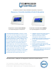

Compressor Controller Installation Guide & Information
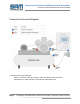
Compresor Controller Model CCR100 and CCR200
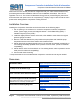
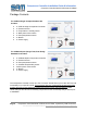
Output Connections Normally Open and Normally Closed Relay outputs
Maximum Ratings AC/DC: (250VAC 10A / 24VDC up to 0.3A)
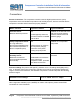
Name / Function
Required / Location
Typical Configuration
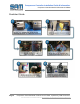
Unloader Valve, Controls
unloader valve based on
pump feedback
Yes.
Located typically where your
mechanical unload valve is
installed
Located typically at
compressor pump output line
and the compressor tank - can
be manual or electrically
actuated.
Normally open solenoid valve
with an orifice (see manual for
details) that provides
depressurization of pump
output
Drain Valve,
Controls drain to minimize
moisture content
Yes.
Located at the bottom of the
tank
Normally closed solenoid
valve, with a line out to drain
the compressor moisture.
(please follow the appropriate
disposal procedures & rules)
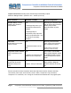
Compressor motor Control,
On/Off compressor pump
motor.
Yes.
Located in an enclosure near /
attached to the compressor.
Connected to a Solid State
Relay (SSR), Magnetic starter
or Variable Frequency Drive
(VFD) that drives the electric
motor.
Auxiliary Fan,
Controls Fan to provide
additional cooling to the
pump
Optional.
Location: Pump or intercooler.
Connected to a Solid State
Relay (SSR) or Magnetic
starter that drives an electric
fan.
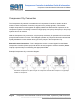
See the manual for further information about the Output Connections, Sensors and other
connections: power input, enclosure fan, buzzer / alarm, Compressor Citty connection,
compressor run connection, aux. cooling fan connection and external halt / stop signal inputs.
Page 7 Compressor Controller Model CCR100
and CCR200
, a product by SAM Controllers
This document can be downloaded at:
samcontrollers.com/download/compressor-install-guide/