9049 Tyler Blvd. • Mentor, Ohio 44060 Phone (440) 974-8888 • Fax (440) 974-0165 Toll-Free Fax 800-841-8003 • buyersproducts.
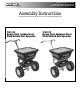
TM 1. Check contents of box against the parts list to make sure all components are included. When ordering replacement or spare parts refer to the parts list for part numbers.
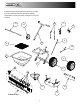
TM TOOLS NEEDED FOR ASSEMBLY Parts List (for all figures) • (2) 10mm Wrenches • (2) ½" Wrenches • (1) Pliers ITEM WB100B 1 3010868 2 3010874 3 3009156 – 3009144 – 3009162 4 3009157 – 3009150 – 3007863 – 3009157* – 3009157* – 3009157* – 3008879 5 3008142 6 3011734 7 3009160 8 3010878 9 3010880 10 3010879 11 3008135 12 3007862 13 3010870 14 3008880 15 3010871 16 3008813 3008881 17 18 3007865 – 3007993 * Must Order Assembly Fastener Selection Guide M6x45 (2) M6x40 (6) M6x40 (4) w/ small washer M6x40 (
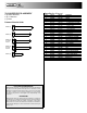
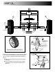
TM 1 M6x45 18 4 18 17 13 SHIM WASHERS COTTER PIN 14 DRIVE GEAR MOUNTING HOLE 2. Loosely assemble the axle components to the Frame(1). A. Position the Spinner Shaft Support(17) and orient it as shown. B. Add two Shim Washers as shown. C. Add four plastic axle Bushings (18). DRIVE WHEEL MOUNTING HOLE COTTER PIN MOUNTING HOLE 3. Position the Spinner Assembly(4) into the Spinner Shaft Support(17) and assemble the parts so that the small gear fits into the Drive Gear(14).
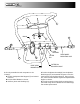
TM 11 12 Shim Washer M6 Nut Cotter Pin M6x45 RIB SIDE MUST FACE AWAY FROM LARGE GEAR COTTER PIN SHIM WASHERS DRIVE WHEEL(11) HAS A HOLE THROUGH THE HUB USED TO MOUNT TO THE AXLE WITH A M6x45 BOLT M6x40 (WITH LARGE WASHERS) 5. Mount the Drive Wheel(11) to the Axle using a m6x45 bolt. Mount the Coast Wheel(12) using shim washers and a cotter pin. Tighten the entire axle assembly as shown. A. Make sure the Bushings are fully seated against the Frame B.
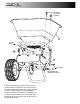
TM (4X) M6x40 WITH SMALL WASHERS 3 SPINNER SHAFT 15 5 15 (2X) M6x40 DRIVE WHEEL NOT SHOWN FOR CLARITY 6. Use two m6x40 bolts to fasten the lower part of the Hopper Support Brackets to the Frame. Position the Spinner Shaft Straight and then using four m6x40 bolts with smaller washers, loosely assemble the Hopper Assembly(3), the Deflector Assembly(5), and the Hopper Support Brackets(15) to the Frame. The Spinner Shaft will go through a hole in the bottom of the Hopper Assembly.
TM MAKE SURE PINION IS MESHED WITH LARGE DRIVE GEAR AND TIGHTEN BOLTS DEFLECTOR NUTS MAY NEED TIGHTENED DEFLECTOR'S WINGNUTS SHOULD BE OUTSIDE OF FLAPS(AWAY FROM SPINNER) 7. Fully tighten the Hopper Assembly to the Frame. 8. Check that the Axle rotates freely, the gears interface well and tighten the Support Bracket to the Frame.
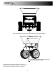
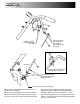
TM 2 Slide Handle Onto Frame And Line Up Holes Attach Control Plate Assembly To Frame Using M6x40 Bolts 8 Secure Bolts & Nuts Snug Against Washers. Controls Must Still Be Able to Pivot. 10 Insert Other End of Lower Linkage Into Control Plate Assembly Insert Lower Linkage Into Restrictor Plate Deflectors Not Shown for Clarity 9. Slide the Handle(2) onto the Frame & line up the holes. 10. Insert the Lower Linkage(10) into the Restrictor Plate pre-attached to the bottom of the Hopper 11.
TM 7 Attach Control Handle Assembly to Frame Using M6x40 Bolts 9 First Jam Nut Remove Control Handle from Assembly, Insert Upper Linkage into Control Handle, Reattach Control Handle 9 Set the Restrictor Plate Fully Open and the Control Handle to "30" (as shown) Thread First Jam Nut onto Upper Linkage and Insert Linkage into Control Plate Assembly Secure Linkage with Second Jam Nut and Tighten 13. Attach the Control Handle Assembly(7) to the Frame using m6x40 bolts. 14.
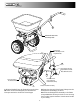
TM 6 M6x20 BOLTS 16.
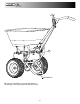
TM 16 17. Double check that all hardware is tight and the drive system turns properly (it should feel a bit snug). 3. Check that the Restrictor Plate and Linkage move freely. Clear out any debris between the Restrictor Plate and the Hopper. 4. Check that there is no debris in the Gears and that they move freely. 5. Check torque of all fasteners on a monthly basis. 18. Place the screen(16) inside the hopper. Operation 1.
9049 Tyler Blvd. • Mentor, Ohio 44060 Phone (440) 974-8888 • Fax (440) 974-0165 Toll-Free Fax 800-841-8003 • buyersproducts.