
Installation Guide

SALSBURY INDUSTRIES
1010 East 62
nd
Street, Los Angeles, CA 90001-1598
Ph: 1-800-624-5269 Int’l Ph: 323-846-6700
Fx: 1-800-624-5299 Int’l Fx: 323-846-6800
www.mailboxes.com engineering@mailboxes.com
Installation instructions are provided as general guidelines. It is advised that a professional installer be consulted. Salsbury Industries assumes no product assembly or installation liability.
Copyright © 2017 Salsbury Industries. All rights reserved. (02/10/17) Page 2 of 2
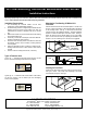
Installing the Mailbox Unit
Lifting and installing the mailbox unit into the enclosure is a two (2)
person operation. Open appropriate compartment doors to provide
handholds. Lift the mailbox unit and carefully slide it into the
enclosure until the front peripheral flange is flush against the front
flanges of the enclosure. See Fig. 6.
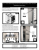
Fastening Mailbox Unit to Enclosure
Open the master doors of the mailbox unit until the hold-open rods at
the top inside corners of the doors engage. Install Type B self-
tapping machine screws (provided) through each counter bored hole
in the bottom flange of the mailbox and through each slotted hole in
the vertical flanges on the sides of the mailbox. See Fig. 7, Fig 8A
and Fig 8B. The number of screws required varies depending on the
height and width of the unit. A maximum height double column unit
is shown.
Close the master doors. The installation is now complete.
Type B
Type B
LEFT
MASTER
DOOR
RIGHT
MASTER
DOOR
BOTTOM
Fig. 6
Fig. 7
Fig. 8A
Mounting
Screw
Location
Mounting
Screw
Location
Type B
Fig. 8B
4C Free-Standing Horizontal Mailboxes–3900 Series
Installation Instructions