
System Description


System Description and Installation Manual for MXS ICD10004-01
© Sagetech Corporation 2018 Confidential Proprietary Export-Controlled Page 5 of 160
Table 6-45 Version Response Message Example Data .................................................................................................... 7667
Table 6-46 ADS-B Report Messages ............................................................................................................................... 7868
Table 6-47 Target Summary Report Message Payload Structure Overview ................................................................... 7969
Table 6-48 Target Summary Report Message Payload Structure Detail ......................................................................... 7969
Table 6-49 ADS-B State Vector Report Message Payload Structure Overview .............................................................. 8070
Table 6-50 ADS-B State Vector Report Message Payload Structure Detail .................................................................... 8171
Table 6-51 ADS-B State Vector Report Message Example Data .................................................................................... 9579
Table 6-52 ADS-B Mode Status Report Message Payload Structure Overview ............................................................. 9680
Table 6-53 ADS-B Mode Status Report Message Payload Structure Detail ................................................................... 9781
Table 6-54 ADS-B Mode Status Report Message Example Data .................................................................................. 11088
Table 6-55 ADS-B Target State Report Message Payload Structure Overview ............................................................ 11289
Table 6-56 ADS-B Target State Report Message Payload Structure Detail .................................................................. 11390
Table 6-57 ADS-B Air Referenced Velocity Report Message Payload Structure Overview ........................................ 12094
Table 6-58 ADS-B Air Referenced Velocity Report Message Payload Structure Detail .............................................. 12194
Table 6-59 TIS-B Report Messages ............................................................................................................................... 12497
Table 6-60 TIS-B Mode Status Report Message Payload Structure Overview ............................................................. 12598
Table 6-61 TIS-B Mode Status Report Message Payload Structure Detail ................................................................... 12699
Table 6-62 TIS-B Coarse Report Message Payload Structure Overview .................................................................... 134105
Table 6-63 TIS-B Coarse Report Message Payload Structure Detail ......................................................................... 135106
Table 6-64 TIS-B Coarse Report Message Example Data ........................................................................................... 140109
Table 6-65 TIS-B/ADS-R Management Report Message Example Data .................................................................... 141110
Table 6-66 Installation Use Case Example Data .......................................................................................................... 145113
Table 6-67 Operational Use Case Example Data ......................................................................................................... 150118
LISTOFFIGURES
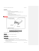
Figure 3-1 MXS Feature Locations ................................................................................................................................... 109
Figure 3-2 51-Pin Micro D-Sub Type Female Main Connector ..................................................................................... 1111
Figure 3-3 Connectors to Top and Bottom Antenna ........................................................................................................ 1212
Figure 3-4 Pressure Altitude Encoder Port to Static Pressure .......................................................................................... 1514
Figure 4-1 – MXS Dimensions ........................................................................................................................................ 1615
Figure 4-2 – Mechanical Connections ............................................................................................................................. 1716
Figure 4-3 MXS Main Connector (Female) Pin Locations .............................................................................................. 1817
Figure 4-4 Transponder Main Connector - Front View ................................................................................................... 1817
Introduction
This document describes the system and provides connection information for the MXS Transponder, part of the Sagetech
MX product family.
NOTE: This document is under development. Additional information and/or modifications may be
provided with future releases.