
System Description

System Description and Installation Manual for MXS ICD10004-01
© Sagetech Corporation 2018 Confidential Proprietary Export-Controlled Page 39 of 160
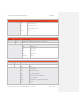
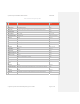
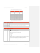
Table 0-10 Operating Message Payload Structure Overview
Payload Index Message Field Number bytes
00
Squawk Code
2
02
Mode/Config
1
03
Emergency/Ident
1
04
Altitude
2
06
Altitude Rate
2
08
Heading
2
10
Airspeed
2
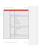
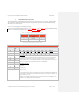
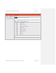
Table 0-11 Operating Message Payload Structure Detail
Squawk Code
Byte Offset
Byte Name Field Description
00
SQK0 Mode A “Squawk” Code – A string of 4 3-bit (octal) numbers, padded with 4 leading zeros.
For example, Squawk 1234 would be formatted as: 0000 001 010 011 100 (0x02:0x9C)
01
SQK1
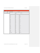
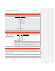
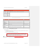
Mode/Config
Byte Offset
Byte Name Field Description
02
MOD0
Mode
The Mode consists of the following information:
Bit 0-1: Operation Mode sets the current Transponder Mode.
00 = Standby
01 = On
11 = ALT
Bit 2: Power Up State. If set to 1, the Mode in this message is stored in non-volatile memory and used
on power up; if set to 0, the Transponder powers up in STBY mode. If the MXS is not in
Maintenance Mode then this assignment is ignored and not acknowledged.
Bit 3: ADS-B Out On (1 = Enable output of Extended Squitters)
Bit 4–7: Reserved