
System Description

System Description and Installation Manual for MXS ICD10004-01
© Sagetech Corporation 2018 Confidential Proprietary Export-Controlled Page 23 of 160
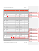
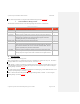
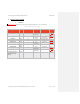
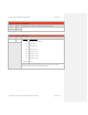
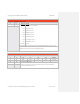
Serial Bus Type/ Required Configuration Main Connector Interface
Ethernet
Ethernet-TX+ 23
Ethernet-RX+ 24
Ethernet-TX- 48
Ethernet-RX- 49
Host Interface Characteristics
11. Communications
MXS is controlled by a straightforward messaging system which communicates over a serial or Ethernet interface.
Communicating with the MXS involves constructing messages, computing a checksum to ensure data validity, and
sending these messages to the MXS.
1. Serial Communication Protocol
MXS’s Main Connector provides two RS-422 or RS-232 serial ports that can be used for operational control and
command. See Table 0-1Table 5-1 for pin numbers and connection information for Com0 and Com1. Table 0-1Table 6-1
provides data rate and format information.
WARNING: If serial communication is being used then only one serial port is used for sending
host messages and for ADS-B In reports. The other RS422/RS232 port is reserved for GPS only
data (if any). Using the same COM port for both GPS and either host messages or ADS-B In
reports will cause unpredictable behavior.
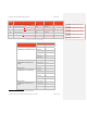
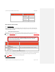
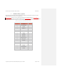
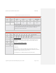
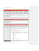
Table 0-1 Serial Communication Protocol Details
COM
Port
Data Rate Data Format
Com0 UseradjustableviaInstallation
Message
38.4KBPSdefault
“8‐N‐1”,1startbit,8databits(Note8),noparity,1stopbit
Com1 UseradjustableviaInstallation
Message
38.4KBPSdefault
“8‐N‐1”,1startbit,8databits(Note8),noparity,1stopbit
2. Ethernet Communication Protocol
Operational control and command messages may also be sent (and replies received) via Ethernet User Datagram Protocol
(UDP) packets. Ethernet bandwidth is required to support the requirement for 400 targets in RTCA/DO-260B.
See Table 0-1Table 5-1 for pin numbers and connection information.
8
Transmitted least significant bit first.