
System Description

System Description and Installation Manual for MXS ICD10004-01
© Sagetech Corporation 2018 Confidential Proprietary Export-Controlled Page 22 of 160
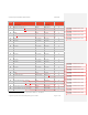
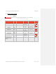
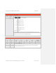
Pin
Number
Signal Direction Signal Char. Required
47
Com1-422-TX- (See note
33
and note
55
) Output RS-422 TX- N
48
Ethernet-TX- (See note
55
) Output IEEE 802.3- N
49
Ethernet-RX- (See note
55
) Input IEEE 802.3- N
50
DC Power (See note
7
) Power 14-28VDC Y
51
DC Power (See note
77
) Power 14-28VDC Y
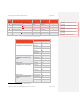
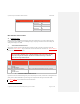
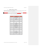
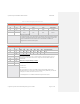
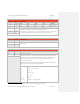
Table 0-2 Communication Port Select Map
Serial Bus Type/ Required Configuration Main Connector Interface
Signal Pin
RS-422 Com0
Com0-Mode pin 17 should be left open
Com0-RX- 44
Com0-RX+ 19
Com0-TX- 45
Com0-TX+ 20
Com0-Mode 17
RS-232 Com0
Com0-Mode pin 17 must be tied to
ground
Com0-232-RX 19
Com0-232-TX 20
Com0-Mode 17
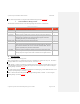
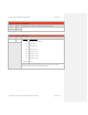
RS-422 Com1
Com0-Mode pin 43 can be left open
Com1-RX- 46
Com1-RX+ 21
Com1-TX- 47
Com1-TX+ 22
Com1-Mode 43
RS-232 Com1
Com1-Mode pin 43 must be tied to
ground
Com1-232-RX 21
Com1-232-TX 22
Com1-Mode 43
7
Both power pins must be connected to aircraft main power.
Formatted: Footnote Reference, Font
color: Auto
Formatted: Footnote Reference, Font
color: Auto
Formatted: Footnote Reference, Font
color: Auto
Formatted: Footnote Reference, Font
color: Auto
Formatted: Footnote Reference