
System Description

System Description and Installation Manual for MXS ICD10004-01
© Sagetech Corporation 2018 Confidential Proprietary Export-Controlled Page 20 of 160
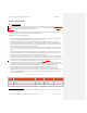
Pin
Number
Signal Direction Signal Char. Required
3
Reserved No Connect Reserved N
4
Reserved No Connect Reserved N
5
Reserved No Connect Reserved N
6
Reserved No Connect Reserved N
7
Reserved No Connect Reserved N
8
Reserved No Connect Reserved N
9
Reserved No Connect Reserved N
10
Reserved No Connect Reserved N
11
Reserved No Connect Reserved N
12
Reserved No Connect Reserved N
13
Reserved No Connect Reserved N
14
GPS-PPS
(See note
2
) Input TTL PPS N
15
Maint Mode Input GND/Open N
16
Weight-on-Wheels Input GND/Open N
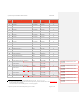
17
Com0-Mode (See note
3
) Input GND/Open N
18
GND
4
Power Ground Y
19
Com0-422-RX+ (See note
33
and note
5
)
Com0-232-RX
Input RS-422 RX+
RS-232 RX
N
20
Com0-422-TX+ (See note
33
and note
55
)
Com0-232-TX
Output RS-422 TX+
RS-232 TX
N
21
Com1-422-RX+ (See note
33
and note
55
)
Com1-232-RX
Input RS-422 RX+
RS-232 RX
N
22
Com1-422-TX+ (See note
33
and note
55
) Output RS-422 TX+ N
2
Pins must be driven or terminated to an appropriate TTL logic level. (0.0 – 0.7 V, or 2.0 – 3.3 V)
3
RS-422 bus will be selected if pins are left unconnected. The pin must be grounded to select RS-232 bus. (See Table 0-2Table 5-2)
4
All four GND pins must be grounded.
5
Transmit and receive are from the MXS perspective. Connect as appropriate.
Formatted: Footnote Reference, Font
color: Auto
Formatted: Footnote Reference, Font
color: Auto
Formatted: Footnote Reference, Font
color: Auto
Formatted: Footnote Reference, Font
color: Auto
Formatted: Footnote Reference, Font
color: Auto
Formatted: Footnote Reference, Font
color: Auto
Formatted: Footnote Reference, Font
color: Auto