
System Description

System Description and Installation Manual for MXS ICD10004-01
© Sagetech Corporation 2018 Confidential Proprietary Export-Controlled Page 19 of 160
Electrical Characteristics
10. Main Connector
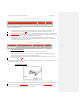
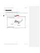
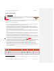
The electrical interface consists of signals brought to the MXS via the 51-Pin Micro-D main connector. Figure 0-4Figure
4-4 presents an image of the female Micro D-Sub Main Connector’s front view, with pin number orientation. Table
0-1Table 5-1 shows the pin assignments for the main connector.
By design, all signals on the main connector are protected from damage caused by Indirect Effects of Lightning (DO-
160G category K3L3
1
) and Electrostatic Discharge (at 2kV HBM or better).
Additional main connector signal information:
Power signals are the supply voltage and ground returns provided by the aircraft. Zener diodes are used on the DC
Power pins to protect the Transponder against overvoltage and reverse polarity.
The Maintenance Mode signal is a discrete input that enables or disables Maintenance Mode. To program the
transponder, Maintenance Mode must be enabled. To enable Maintenance Mode, connect the Maintenance Mode
signal to ground. During normal operation Maintenance Mode should be disabled. To disable Maintenance Mode,
leave the Maintenance Mode signal unconnected, i.e. floating.
MXS Power Control signal is used to shut the Transponder off (near zero power consumption). If the Power Control
line is left open, the Transponder will be on. If the power control line is shorted to ground, the Transponder will be
off.
Weight-on-Wheels (WOW) signal is an input that indicates to the Transponder whether the aircraft is on the ground
or in the air. Grounding the pin indicates that the aircraft is on the ground. Removing the ground will indicate the
aircraft is in the air. If the WOW signal is not used, the pin may be left unconnected.
The communication ports (Com0 and Com1) can be configured as either a RS-232 or RS-422 serial bus. Selecting the
serial communication port bus type and Main Connector pin interface is controlled by the state of Com0-Mode and
Com1-Mode. The Com-Mode pins are weakly pulled up to 3.3Vdc and will select RS-422 if left unconnected. A truth
table based on the state of Com0-Mode and Com1-Mode is provided in Table 0-2Table 5-2.
At least one COM bus or Ethernet must be selected and used for the Host Computer Command and Control interface.
Mutual Suppress is designed to connect to an aircraft’s bidirectional suppression bus. Mutual Suppression bus is used
to desensitize L-Band receivers and block L-Band transmitters when another onboard L-Band equipment is
transmitting. This prevents interferences from own-ship L-Band transmitters. It is typically used when aircraft
equipage includes Transponders, TCAS and/or DME. MXS stops transmitting and receiving when Mutual
Suppression line is driven to high (18V-70V) by an external source. The MXS will return to normal operation within
15 microseconds following the suppression pulse. The Mutual Suppression bus follows the design requirements of
the ARINC 718 specification.
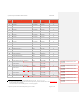
Table 0-1 MXS Main Connector Pin Assignments
Pin
Number
Signal Direction Signal Char. Required
1
Reserved No Connect Reserved N
2
Reserved No Connect Reserved N
1
Section 22 Waveform 3 Level 3 and Waveform 1 Level 1. A Shielded cable harness built according to Standard A-A 59569A will
be required to meet these categories.