
System Description

System Description and Installation Manual for MXS ICD10004-01
© Sagetech Corporation 2018 Confidential Proprietary Export-Controlled Page 15 of 160
6. Routing and connecting the antenna cable
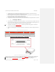
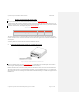
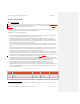
Attach your antenna cable to the bottom antenna SMA connector shown in Figure 0-3Figure 3-3.
A suitable antenna cable consists of a male SMA connector, a length of co-axial cable, and a suitable connector for your
antenna. For example, if you are using a simple monopole antenna with a BNC female connector, your antenna cable will
need a BNC male connector. (See example cable part in Table 0-5Table 3-5.)
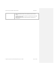
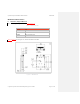
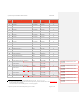
Table 0-5 Antenna Cable Connector Parts
Part Description Manufacturer Part Number
SMA Male to BNC Male Right Angle Cable 24”
Sagetech 10-1639
The antenna cable must have no more than 2dB of signal loss from the MXS to the antenna. This includes losses in the
connector and cable. Generic and custom-built cables can be obtained from suppliers such as Pasternak, Richardson, and
Aircraft Spruce.
Avoid sharp bends in the antenna cable that could lead to additional cable loss.
7. Connecting altitude sensor/encoder to system Static Pressure
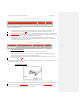
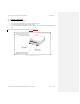
Figure 0-4 Pressure Altitude Encoder Port to Static Pressure
MXS has an altitude encoder port. (See Figure 0-4Figure 3-4.) Altitude data for the extended squitter can be based on
MXS’s integral, calibrated pressure sensor and encoder (termed a blind encoder).
Plumb the altitude encoder connection to a static pressure line that shares the same source as the main aircraft altimeter.
The pressure barb is sized for 3/16” Internal Diameter (ID) tubing. A typical installation will have a T or Y fitting in the
static pressure line with one end running to the MXS. Suitable Y-barbed tube fittings are available from suppliers such as
McMaster-Carr.