
System Description

System Description and Installation Manual for MXS ICD10004-01
© Sagetech Corporation 2018 Confidential Proprietary Export-Controlled Page 12 of 160
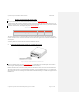
Table 0-2 Main Connector Part Description
Part Description Manufacturer Part Number
Female Power and Interface Connector Micro-D 51 pin, 2-row
Omnetics A99601-512
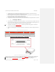
To connect to the Main Connector:
Construct a cable to connect the host computer to the Main Connector according to pin-out definitions and
instructions described in Section 05.0. The cable should be built according to standard A-A 59569A.
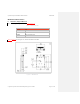
The MXS can be powered with 14-28 VDC +/- 4 VDC (at the MXS). MXS power consumption is documented in
Table 0-3Table 3-3. If you are supplying voltage to the MXS at the lower end of that range, avoid voltage loss by
using short power supply wires and/or larger diameter power supply wires.
Zener diodes are used on the DC Power pins to protect the MXS against overvoltage and reverse polarity.
Surge currents can be up to 5A when enabling operating mode or transmitting. The in-rush current at power-on
(in operating mode) will also not exceed 5A.
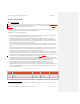
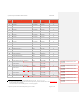
Table 0-3 Maximum Current Consumption
Variant SupplyVoltage MaxAverageCurrent Note
MXS 14V 2.1A Measured
28V 1.0A Measured
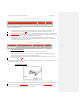
4. Connect to GPS Interface
GPS data should be provided to the MXS from the aircraft system integrator in one of two ways:
a) GPS serial data stream on the 51-pin Micro-D connector. The data format is either NMEA or a proprietary
format from a NexNav Mini GPS (a TSO-C145c compliant solution).
b) Host Computer GPS data is incorporated into the command and control protocol packets on the 51-pin serial
interface. (See Section 105.1.)
Note: Sagetech recommends using the external Accord Technology NexNav Mini receiver. It is the smallest TSO-C145c
compliant receiver Sagetech has identified.
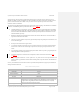
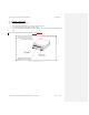
5. Installing two Antennas
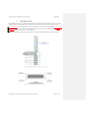
Figure 0-3 Connectors to Top and Bottom Antenna
In the diversity configuration, top and bottom-located antennas should be connected to MXS using the left and right-side
female SMA connectors (see Figure 0-3Figure 3-3). Assuming the orientation shown in Figure 0-3Figure 3-3, the top