
System Description

System Description and Installation Manual for MXS ICD10004-01
© Sagetech Corporation 2018 Confidential Proprietary Export-Controlled Page 11 of 160
The MXS requires a 2.0°C/Watt heat sink at full power above 40°C ambient. Actual heat sink needs are
dependent on temperature of operating environment and power load.
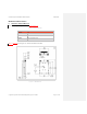
MXS is designed in such a way that its case conducts thermal load to the aircraft frame. It can be firmly mounted
directly to the aircraft or to other components within the aircraft.
MXS should be mounted with the non-labeled side facing the heat sink.
If inadequate heat sinking is provided, the MXS will not transmit while internal temperature limits are exceeded.
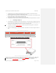
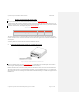
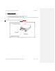
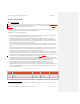
3. Mounting the MXS Unit
The mounting holes in the MXS are found on the top of the unit. The two holes closer to the Main Connector are
24 mm in depth at the mounting points, while the two further away are 20 mm depth at the mounting points. All
four holes are 3.35 mm in diameter and accept 4-40 (or M3 x .05) machine screws.
The machine screws listed in Table 0-1Table 3-1 represent an approximate starting point in a search for the
correct screw for your custom installation.
Sagetech recommends applying Loctite 242 Threadlocker to the machine screw threads or using lock washers or
nuts.
Table 0-1 Common mounting parts/vendors
Quantity
Required
Description Vendor VendorPN
4 11/4"PanHead4‐40MachineScrew McMaster‐Carr 90279A117
8 Washers McMaster‐Carr 98029A024
4 LockNuts McMaster‐Carr 90631A005
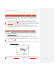
3. Route power cables and Host Computer to the MXS
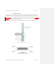
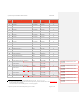
Figure 0-2 51-Pin Micro D-Sub Type Female Main Connector
The Main Connector carries power as well as serial and Ethernet communications to the host computer. MXS’s Main
Connector is a 51-pin Micro D-Sub type female connector. Figure 0-2Figure 3-2 shows the Main Connector pin
assignment orientation. Table 0-2Table 3-2 provides the Main Connector manufacturer’s part number.