
System Description

SystemDescriptionandInstallationManualforRangeFinder ICD10000‐01
©SagetechCorporation2018ConfidentialProprietaryExportControlled Page24of130
8.0 HostInterfaceCharacteristics
8.1 Communications
Range Finder is controlled by a straightforward messaging system which communicates over a serial or
Ethernet interface.Communicating with the Range Finder involves constructing messages, computing a
checksumtoensuredatavalidity,andsendingthesemessagestotheRangeFinder.
8.1.1 SerialCommunicationProtocol
Range Finder’s Main Connector provides two RS‐422 or RS‐232 serial ports that can be used for operational
controlandcommand.SeeTable7‐1forpinnumbersandconnectioninformationforCom0andCom1.Table
8‐1providesdatarateandformatinformation.
Ifserialcommunicationisbeingused
thenonlyoneserialportisusedforsendinghostmessages.Theother
RS422/RS232portisreservedforGPSonlydata(ifany).
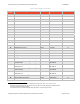
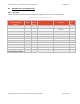
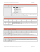
Table8‐1SerialCommunicationProtocolDetails
COM
Port
DataRate DataFormat
Com0 UseradjustableviaInstallation
Message
38.4KBPSdefault
“8‐N‐1”,1startbit,8databits
(Note8),noparity,1stopbit
Com1 UseradjustableviaInstallation
Message
38.4KBPSdefault
“8‐N‐1”,1startbit,8databits
(Note8),noparity, 1stopbit
8.1.2 EthernetCommunicationProtocol
Operational control and command messages may also be sent (and replies received) via Ethernet User
DatagramProtocol(UDP)packets.Ethernetbandwidthisrequiredtosupporttherequirementfor400targets
in
RTCA/DO‐260B.
SeeTable7‐1forpinnumbersandconnectioninformation.
TheIPaddressandportnumberarecon f iguredintheinstallationmessage(Section8.3.2).
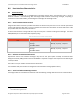
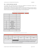
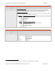
8.1.3 SerialandEthernetMessageFormat
TheRangeFinderserialandEthernetinterfaceusesthefollowingmessagedatastructureforcommunication:
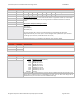
wer.
8
Transmittedleastsignificantbitfi