
System Description

SystemDescriptionandInstallationManualforRangeFinder ICD10000‐01
©SagetechCorporation2018ConfidentialProprietaryExportControlled Page20of130
7.0 ElectricalCharacteristics
7.1 MainConnector
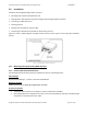
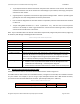
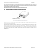
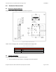
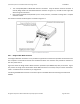
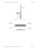
TheelectricalinterfaceconsistsofsignalsbroughttotheRangeFinderviathe51‐PinMicro‐Dmainconnector.
Figure 6‐4 presents an image of the female Micro D‐Sub Main Connector’s front view, with pin number
orientation.Table7‐1showsthepinassignmentsforthemainconnector.
By
design,allsignalsonthemainconnectorareprotectedfromdamagecausedbyIndirectEffectsofLightning
(DO‐160GcategoryK3L3
1
)andElectrostaticDischarge(at2kVHBMorbetter).
Additionalmainconnectorsignalinformation:
Power signals are the supply voltage and ground returns provided by the aircraft. Zener diodes are
usedontheDCPowerpinstoprotecttheRangeFinderagainstovervoltageandreversepolarity.
The Maintenance Mode
s ignal is a discrete input that enables or disables Maintenance Mode. To
program the Range Finder, Maintena nce Mode must be enabled. To enable Maintenance Mode,
connect the Maintenance Mode signal to ground. During normal operation Maintenance Mode
shouldbedisabled.TodisableMaintenanceMode,leavetheMaintenanceModesignalunconnected,
i.e.floating.
MXPowerControl signalisusedtoshuttheRangeFinder off(nearzero powerconsumption).If the
Power Control line is left open, the Range Finder will be on.If the power control line is shorted to
ground,theRangeFinderwillbeoff.
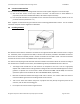
Weight‐on
‐Wheels(WOW)signalisaninputthatindicatestotheRangeFinderwhethertheaircraftis
onthegroundor in theair.Grounding thepin indicatesthattheaircraftis on theground.Removing
the ground will indicate the aircraft is in the air. If the WOW signal is
not used, the pin may be left
unconnected.
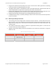
Thecommunicationports(Com0andCom1)canbeconfiguredaseitheraRS‐232orRS‐422serialbus.
Selecting the serial communication port bus type and Main Connector pin interface is controlled by
the state of Com0 ‐Mode and Com1‐Mode.
The Com‐Mode pins are weakly pulled up to 3.3Vdc and
will select RS‐422 if left unconnected. A truth table based on the state of Com0 ‐Mode and Com1‐
ModeisprovidedinTable7‐1.
Atleast one COM bus or Ethernet must be selected and used
forthe Host Computer Command and
Controlinterface.
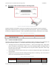
Mutual Supp ress is designed to connect to an aircraft’s bidirectional suppression bus. Mutual
Suppressionbus is used to desensitizeL‐Band receiversand blockL‐Band transmitterswhenanother
onboard L‐Band equipment is transmitting. This prevents interferences from own‐ship L
‐Band
transmitters. It is typically used when aircraft equipage includes Transponders, TCAS and/or DME.
Range Finder stops transmitting and receiving when Mutual Suppression line is driven to high (18V‐
70V)byanexternalsource.TheRangeFinderwillreturntonormaloperationwithin15microseconds
followingthe suppression pulse.The
MutualSuppressionbus followsthedesi gn requirements ofthe
ARINC718specification.
1
Section22Waveform3Level3andWaveform1Level1.AShieldedcableharnessbuiltaccordingtoStandardA‐A59569Awillbe
requiredtomeetthesecategories.